Electromagnetic induction is the process by which a changing magnetic field produces an electric current in a conductor, discovered independently by Michael Faraday and Joseph Henry in 1831. This chapter explains how induced e.m.f. arises, magnetic flux and Faraday's law, Lenz's law, and how these principles power the A.C. generator and the transformer, including step-up and step-down designs and the turns-ratio equation.
It also covers the deflection of electron beams by electric and magnetic fields, how a cathode ray oscilloscope (CRO) displays waveforms, why the sky is blue during the day and red at sunset (scattering of light), and the particle nature of light — photons, the photoelectric effect, and radiation pressure used in solar sails.
Learning Objectives
- Describe an experiment to demonstrate electromagnetic induction, and state the factors affecting the magnitude of induced e.m.f.
- Define magnetic flux (φ = BA cosθ) and state Faraday's law of electromagnetic induction (ε = -N Δφ/Δt)
- State and apply Lenz's law, and relate it to the law of conservation of energy
- Describe how an A.C. generator works, including the role of slip rings and brushes, and sketch e.m.f.-time graphs
- Explain the principle of operation of a simple iron-cored transformer, and use the terms primary, secondary, step-up, and step-down
- Use the turns-ratio equation Vs/Vp = Ns/Np to solve transformer problems
- Describe the deflection of an electron beam by electric and magnetic fields, and apply Fleming's left-hand rule
- Interpret waveforms on an oscilloscope, and describe the role of the saw-tooth wave in the time base
- State the speed of electromagnetic waves in vacuum and air, and explain qualitatively why the sky is blue and sunsets are red
- State that light can be considered as photons carrying energy and momentum, and describe evidence for this (photoelectric effect, radiation pressure, solar sails)
Key Concepts
18.1 Electromagnetic Induction
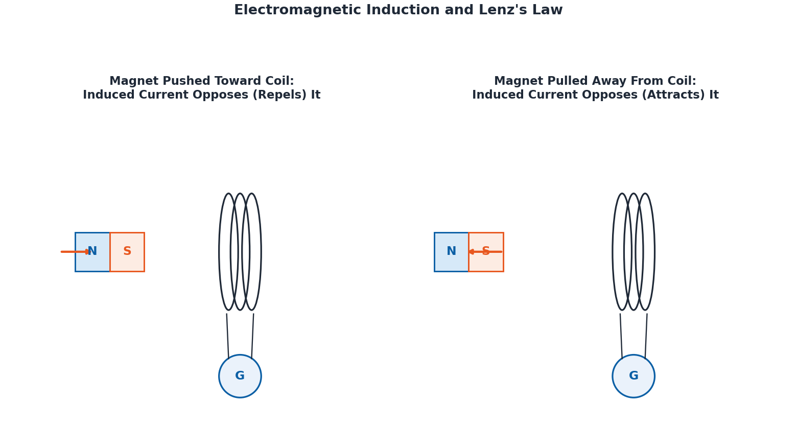
Electromagnetic induction is the process by which a changing magnetic field produces an electric current in a conductor, first discovered by Michael Faraday and, at the same time, Joseph Henry, in 1831. This principle is fundamental to generators, transformers, and inductors. In a simple experiment, a coil C is connected to a galvanometer G: when a magnet is held still near the coil, the galvanometer shows no deflection, since there is no change in the magnetic field. When the magnet is moved towards the coil, the galvanometer deflects in one direction, showing current is produced; when the magnet is moved away, the galvanometer deflects in the opposite direction, showing the current has reversed.
A similar effect is seen by moving a straight wire (forming a closed loop with a galvanometer) through the field of a permanent magnet: no current flows while the loop is still, but as it moves and cuts through the magnetic field lines, current flows, and reversing the direction of motion reverses the direction of the current. The induced current depends on how fast the wire moves and the loop's resistance; experimentally, the product of the current I and resistance R remains constant for a given speed — this constant value is the induced e.m.f. The induced current (or e.m.f.) can be increased by: using a stronger magnetic field, moving the loop/magnet more quickly, or using a coil with many turns instead of a single loop. It is the relative motion between the conductor and the magnetic field that produces the induced e.m.f., and this motion is what changes the magnetic flux through the loop.
18.2 Magnetic Flux and Faraday's Law
Magnetic flux is the number of magnetic field lines passing through a given area, given by φ = BA cosθ, where B is the magnetic field strength, A is the area of the coil, and θ is the angle between the field and the normal to the coil's plane. The SI unit of magnetic flux is the weber (Wb), where 1 Wb = 1 T m² — one weber is the flux when a field of 1 tesla passes perpendicularly through an area of 1 m². Flux is maximum when the field is perpendicular to the coil's plane (θ = 0°) and zero when the field lies in the plane of the coil (θ = 90°).
Faraday's law of electromagnetic induction states that the average e.m.f. induced in a coil of N turns equals the negative of the rate at which the magnetic flux changes with time: ε = -N Δφ/Δt, where the negative sign indicates that the induced e.m.f. opposes the change in flux that produces it. Worked Example: a coil with 25 turns experiences a constant induced e.m.f. of 2.5 V for 0.20 s; the change in flux is Δφ = (ε × Δt)/N = (2.5 × 0.20)/25 = 0.02 Wb.
18.3 Lenz's Law
Lenz's law states that the direction of an induced current is always such that it opposes the cause which produces it — this is a direct consequence of the conservation of energy, since an induced current that reinforced the change instead of opposing it would lead to a perpetual (and impossible) increase in energy. When a changing magnetic field near a conductor induces an e.m.f., the resulting current generates its own magnetic field that counteracts the original change in flux: if a magnet is pushed toward a coil, the induced current creates a field that repels the magnet, resisting its motion; if the magnet is pulled away, the induced current creates a field that attracts the magnet, again opposing the movement. The faster a magnet is moved through a coil, the greater the induced e.m.f. — this principle underlies wind turbines and bicycle dynamos.
18.4 A.C. Generator
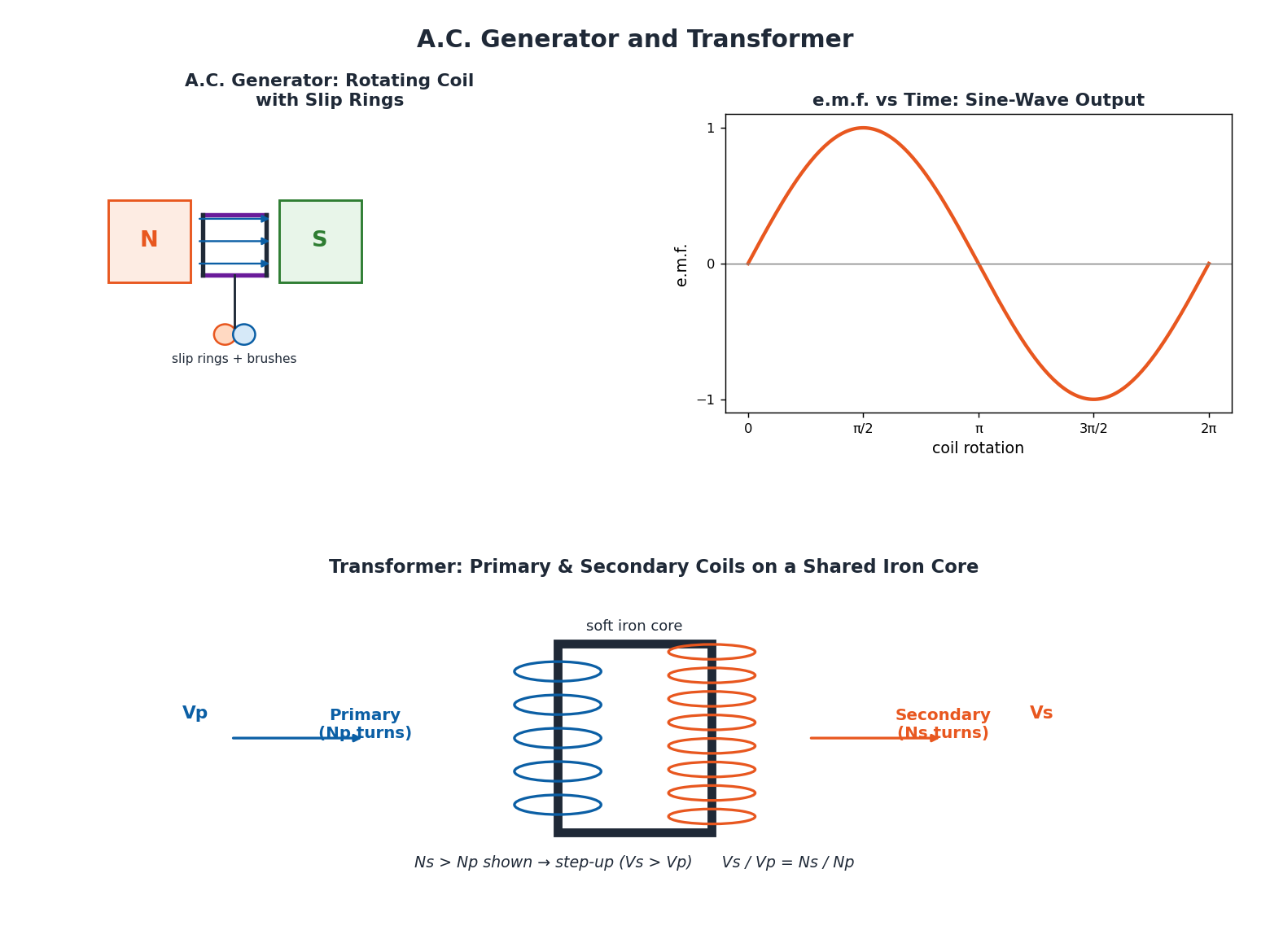
An alternating current (A.C.) generator converts mechanical energy into electrical energy using electromagnetic induction. Its basic form has a rectangular coil placed between the poles of a permanent magnet, connected to two slip rings that rotate along with the coil; fixed carbon brushes maintain contact with the slip rings to transfer the generated current to the external circuit. As the coil rotates, it cuts the magnetic field lines, inducing a voltage; a faster rotation cuts the field lines faster, producing a larger induced voltage.
When the coil is vertical, it moves along the field lines without cutting them, so the induced voltage is zero; as it rotates to horizontal, it cuts the field lines at the maximum rate, producing maximum voltage. After a half-turn, the direction of the coil's motion through the field reverses, so the voltage's polarity switches — this continuous reversal produces alternating current. The e.m.f.-time graph is a sine wave: at 0 and π radians (0° and 180°) the coil is vertical and e.m.f. is zero; at π/2 (90°) the coil is horizontal and e.m.f. is at its positive maximum; at 3π/2 (270°) e.m.f. reaches its negative maximum. The number of complete cycles per second is the frequency, measured in hertz (Hz) — A.C. mains in Pakistan alternates at 50 Hz.
18.5 Transformer
A transformer changes (increases or decreases) the voltage in an A.C. circuit, without any direct electrical connection between its input and output coils. It consists of a primary coil (Np turns) and a secondary coil (Ns turns), both wound on a shared soft iron core that carries the magnetic field from one coil to the other. An alternating voltage Vp applied to the primary coil drives an alternating current Ip, producing a changing magnetic field in the iron core; this field passes through the secondary coil and induces an alternating voltage Vs (and current Is) there — energy is transferred through the magnetic field in the core, with no direct electrical connection between the coils.
When the secondary coil has more turns than the primary, output voltage is increased — a step-up transformer; when the secondary has fewer turns than the primary, output voltage is reduced — a step-down transformer. This relationship is described by the turns-ratio equation: Vs/Vp = Ns/Np. Step-up transformers raise voltage for efficient long-distance power transmission (lower current at higher voltage means lower power loss, P = I²R, in the cables), while step-down transformers reduce voltage to safe levels for use in homes. Worked Example: electricity transmitted at 20,000 V with a current of 5 A through cables of resistance 10 Ω loses power P = I²R = (5)² × 10 = 250 W.
18.6 Deflection of Electron Beams in Electric and Magnetic Fields
Cathode rays generated from an electron gun are high-speed, negatively charged electrons. In an electric field, each electron is attracted toward the positive electrode and repelled by the negative electrode, so cathode rays are deflected toward the positive electrode in the presence of an electric field. In a magnetic field, since a magnetic field exerts a force on any moving charged particle, the electron beam is deflected as it passes through the field; the direction of this deflecting force can be found using Fleming's left-hand rule.
18.7 Waveform on Oscilloscope
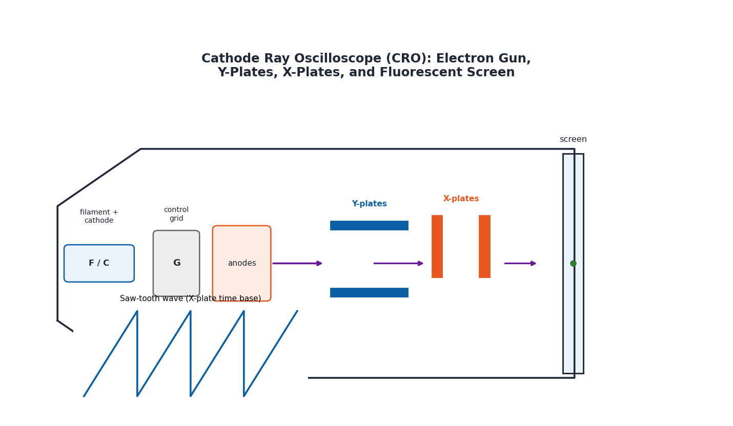
A Cathode Ray Oscilloscope (CRO) displays, observes, and measures how electrical signals change with time. Its main component is the cathode ray tube (CRT), which includes an electron gun, a deflecting system, and a fluorescent screen. The electron gun contains a heated filament F that heats the cathode C, causing it to emit electrons, which are then accelerated and focused by three anodes at high positive potential; a control grid G at negative potential controls how many electrons reach the screen, adjusting the brightness of the displayed spot. The deflecting system has two pairs of plates: Y-plates (control vertical movement, based on the input signal) and X-plates (control horizontal movement).
The fluorescent screen glows where the electron beam strikes it, tracing the waveform of the signal. To sweep the spot steadily across the screen, the CRO applies a saw-tooth wave to the X-plates — a voltage that increases steadily and then rapidly drops back to its starting value, repeating continuously, which creates a regular time axis on the screen. When a sine wave signal is applied to the Y-plates while the saw-tooth voltage drives the X-plates, the beam traces the shape of the signal in real time; the display appears stable only when the saw-tooth (time base) frequency equals or is a multiple of the input signal's frequency. CROs can display waveform shape, measure amplitude, determine time period and frequency, and compare the phase difference between two signals — essential tools in electronics, physics, and medical diagnostics.
18.8 Scattering of Light in the Atmosphere
The sky's blue daytime colour and its reddish appearance at sunset both result from the scattering of sunlight in the Earth's atmosphere. Sunlight contains all the colours of the visible spectrum; as it passes through the atmosphere, it interacts with tiny gas molecules, and blue light — having a shorter wavelength — scatters more easily than red or green light. During the day, this scattered blue light reaches us from all directions, making the sky appear blue.
During sunrise or sunset, sunlight must travel a much longer path through the atmosphere before reaching an observer; by that point, most of the blue light has already been scattered away, leaving mainly the longer wavelengths (red and orange), which scatter less and dominate the sky near the horizon, producing the characteristic warm reddish hues. Dust, pollution, and water droplets in the atmosphere can further enhance this scattering, making sunsets appear even more dramatic, with deep reds and purples.
18.9 Particle Nature of Light
While light is commonly understood as a wave, it also exhibits particle-like behaviour: according to modern physics, light can be viewed as a stream of massless particles called photons, which carry energy and momentum despite having no rest mass. Key evidence for this is the photoelectric effect: when light shines on a metal surface, it can transfer energy to electrons, and if the energy is sufficient, electrons (called photoelectrons) are ejected from the surface — this proves that light energy arrives in discrete packets (photons) rather than as a continuous wave.
Another example is radiation pressure: light exerts a tiny force when it strikes an object. Though very small, this force has real applications — solar sails on some spacecraft are designed to reflect sunlight, and the momentum carried by the reflected photons gradually pushes the sail forward, propelling the spacecraft through space without using any fuel. This dual behaviour — acting as both a wave and a particle depending on how it interacts with matter — is one of the most fascinating ideas in modern physics.
Important Definitions
Define electromagnetic induction.
The process by which a changing magnetic field produces an electric current in a conductor, discovered by Michael Faraday and Joseph Henry in 1831.
Define magnetic flux.
The number of magnetic field lines passing through a given area: φ = BA cosθ, measured in weber (Wb), where 1 Wb = 1 T m².
State Faraday's law of electromagnetic induction.
The average e.m.f. induced in a coil of N turns equals the negative of the rate of change of magnetic flux with time: ε = -N Δφ/Δt.
State Lenz's law.
The direction of induced current is always such that it opposes the cause which produces it — a consequence of the law of conservation of energy.
What is a transformer?
A device that increases or decreases alternating voltage using electromagnetic induction between a primary and secondary coil wound on a shared iron core, with no direct electrical connection between them.
Differentiate a step-up transformer from a step-down transformer.
A step-up transformer has more turns in the secondary coil than the primary, increasing output voltage; a step-down transformer has fewer turns in the secondary, decreasing output voltage.
What is a cathode ray oscilloscope (CRO)?
An electronic instrument that uses an electron beam, deflecting plates, and a fluorescent screen to display, observe, and measure how electrical signals change with time.
Define a photon.
A massless particle that carries a discrete packet of energy and momentum, representing the particle-like nature of light.
Key Formulas
| Topic | Formula |
|---|---|
| Magnetic flux | φ = BA cosθ |
| Weber (unit of flux) | 1 Wb = 1 T m² |
| Faraday's law of induction | ε = -N Δφ/Δt |
| Induced e.m.f. from current and resistance | I × R = constant (= induced e.m.f. ε) |
| Transformer turns-ratio equation | Vs / Vp = Ns / Np |
| Power loss in transmission cables | P = I²R |
| Speed of electromagnetic waves in vacuum/air | c = 3.0 × 10⁸ m s⁻¹ |
| A.C. frequency | f (Hz) = number of complete cycles (coil rotations) per second |
Diagrams
Electromagnetic Induction and Lenz's Law: A bar magnet moving into and out of a coil connected to a galvanometer, showing the induced current direction opposing the magnet's motion in each case
A.C. Generator and Transformer: A rotating coil A.C. generator with slip rings and its sinusoidal e.m.f.-time graph, alongside a simple transformer with primary and secondary coils wound on a shared iron core
Cathode Ray Oscilloscope (CRO): The main components of a CRO — electron gun, control grid, Y-plates and X-plates, and fluorescent screen — with a saw-tooth time-base waveform
Short Questions & Answers
What is the direction of induced current according to Lenz's law?
The induced current always flows in a direction such that it opposes the change (cause) that produced it — a direct result of the conservation of energy.
Why are slip rings used in an A.C. generator?
Slip rings rotate along with the coil and, together with fixed carbon brushes, maintain continuous electrical contact, allowing the alternating current generated in the rotating coil to be transferred to the external circuit.
When is the induced e.m.f. zero in an A.C. generator?
The induced e.m.f. is zero when the coil is in the vertical position, since at that instant it moves along the magnetic field lines without cutting them, so no flux is being cut.
Why is the sky red at sunset?
At sunset, sunlight travels a much longer path through the atmosphere; most of the shorter-wavelength blue light is scattered away before reaching the observer, leaving the longer-wavelength red and orange light, which scatters less and dominates near the horizon.
What is a transformer, and on what principle does it work?
A transformer is a device that increases or decreases alternating voltage; it works on the principle of electromagnetic (mutual) induction — a changing current in the primary coil produces a changing magnetic field in the iron core, which induces a voltage in the secondary coil.
State the turns-ratio equation for a transformer and define its terms.
Vs/Vp = Ns/Np, where Vp and Vs are the primary and secondary voltages, and Np and Ns are the number of turns in the primary and secondary coils respectively.
What is the SI unit of magnetic flux, and how is it defined?
The weber (Wb); one weber is the magnetic flux when a magnetic field of 1 tesla passes perpendicularly through an area of 1 square metre (1 Wb = 1 T m²).
What evidence supports the particle nature of light?
The photoelectric effect (light ejecting electrons from a metal surface only in discrete energy packets) and radiation pressure (light exerting a small force on objects, as used in solar sails) both provide evidence that light behaves as photons.
Long Questions & Answers
Describe an experiment that demonstrates electromagnetic induction, and explain the factors that affect the magnitude of the induced e.m.f.
Electromagnetic induction — the production of an electric current in a conductor by a changing magnetic field — can be demonstrated using a coil of conducting wire C connected to a sensitive galvanometer G, with a bar magnet held nearby. When the magnet is held completely still near the coil, the galvanometer needle does not move at all, showing that no current is produced; this is because there is no change occurring in the magnetic field linking the coil. When the magnet is then moved towards the coil, the galvanometer needle deflects in one particular direction, indicating that a current is now flowing through the coil. If the magnet is instead moved away from the coil, the galvanometer needle deflects in the opposite direction, showing that the induced current has reversed direction. A closely related experiment uses a straight conducting wire forming a closed loop (with a galvanometer) placed in the magnetic field of a permanent magnet: when the loop is stationary, no current flows, but as the loop is moved through the field, the wire cuts across the magnetic field lines and a current is induced, which stops the instant the motion stops, and reverses direction if the direction of motion is reversed. In both experiments, it is specifically the relative motion between the conductor and the magnet — not the motion of either one alone — that produces the induced e.m.f., because this relative motion is what changes the magnetic flux linking the circuit; a stationary magnet near a stationary coil produces unchanging flux and therefore no induced current, no matter how strong the magnet is. Several factors affect the magnitude of the induced current or e.m.f.: it increases with the strength of the magnetic field used (a stronger magnet induces a larger e.m.f.), it increases with the speed at which the loop or magnet is moved (faster relative motion means a faster rate of change of flux, and thus a larger induced e.m.f., as described by Faraday's law), and it increases with the number of turns in the coil (a coil with many turns links more flux changes simultaneously and produces a proportionally larger total induced e.m.f. than a single loop).
State Faraday's law of electromagnetic induction and Lenz's law, and explain how Lenz's law is a direct consequence of the law of conservation of energy.
Faraday's law of electromagnetic induction states that the average e.m.f. induced in a coil of N turns is equal to the negative of the rate at which the magnetic flux linking the coil changes with time, expressed mathematically as ε = -N Δφ/Δt, where ε is the induced e.m.f. in volts, N is the number of turns, and Δφ/Δt is the rate of change of magnetic flux. This equation shows that a faster-changing flux, or a coil with more turns, both produce a larger induced e.m.f. Lenz's law addresses the direction (rather than the magnitude) of the induced current, stating that the direction of an induced current is always such that it opposes the cause which produces it — this is why a negative sign appears in Faraday's law equation. To see why this must be a consequence of energy conservation, consider what would happen if the induced current instead reinforced (rather than opposed) the change producing it: if, for example, pushing a magnet toward a coil induced a current that attracted the magnet further inward rather than repelling it, the magnet would accelerate into the coil without any external work being done, continually increasing the system's kinetic and electrical energy from nothing — a violation of the fundamental principle that energy cannot be created from nothing. Instead, because the induced current always opposes the motion or change producing it (for instance, generating a magnetic field that repels an approaching magnet, or attracts a receding one), an external agent must always do work against this opposition to keep the magnet moving, and it is precisely this external work that is converted into the electrical energy of the induced current — ensuring that energy is properly conserved rather than spontaneously created.
Explain the working principle of a simple iron-cored transformer, and derive/explain the turns-ratio equation relating primary and secondary voltages to the number of turns in each coil.
A transformer is a device used to increase or decrease the voltage of an alternating current supply, and it achieves this entirely through electromagnetic induction, without any direct electrical connection between its input and output circuits. A simple transformer consists of two separate coils of wire — the primary coil, with Np turns, and the secondary coil, with Ns turns — both wound around a common soft iron core, which serves to efficiently carry (channel) the magnetic field produced by one coil through to the other coil. When an alternating voltage Vp is applied across the primary coil, it drives an alternating current Ip through that coil; because this current is continuously changing direction and magnitude, it produces a continuously changing magnetic field within the iron core. This changing magnetic field passes through the core and links with the secondary coil as well, and by Faraday's law, this changing flux through the secondary coil induces an alternating e.m.f. (voltage) Vs across it, which in turn drives an alternating current Is through any circuit connected to the secondary coil. At no point do electrons or current actually flow directly between the primary and secondary circuits; energy is transferred purely through the medium of the oscillating magnetic field in the shared iron core. Because the magnetic flux is essentially the same through every turn of both coils (assuming an efficient iron core with minimal flux leakage), each individual turn — whether in the primary or secondary coil — has the same e.m.f. induced in it; therefore, a coil with more total turns will have a proportionally larger total induced voltage across it than a coil with fewer turns, giving the turns-ratio equation Vs/Vp = Ns/Np. If the secondary coil is wound with more turns than the primary coil (Ns > Np), the secondary voltage will be larger than the primary voltage, and the transformer is called a step-up transformer; conversely, if the secondary coil has fewer turns than the primary (Ns < Np), the secondary voltage will be smaller, and the transformer is called a step-down transformer. Step-up transformers are used to raise voltage to very high levels for efficient long-distance electricity transmission (since transmitting at high voltage and correspondingly lower current reduces resistive power losses, P = I²R, in the cables), while step-down transformers are used near the point of consumption to reduce this high transmission voltage back down to safe levels suitable for use in homes and businesses.
Explain why the sky appears blue during the day but red at sunset, and describe how light can be understood as having a particle nature, giving one piece of supporting evidence.
The colours we see in the sky both during the day and at sunset arise from the scattering of sunlight by the tiny gas molecules that make up Earth's atmosphere. Sunlight itself is not a single colour but a mixture of all the colours of the visible spectrum — red, orange, yellow, green, blue, indigo, and violet — each corresponding to a different wavelength of light. As sunlight passes through the atmosphere, it interacts with and scatters off these gas molecules, and this scattering process is far more effective for shorter-wavelength light (such as blue) than for longer-wavelength light (such as red); blue light is therefore scattered many times more strongly than red light as it travels through the air. During the middle of the day, sunlight has a relatively short, direct path through the atmosphere to reach an observer on the ground, and the strongly scattered blue light is scattered repeatedly in all directions across the sky, meaning that no matter which direction an observer looks (away from the Sun itself), they see this scattered blue light arriving from that portion of the sky — this is why the sky appears blue overhead throughout the day. However, near sunrise and sunset, the Sun's position close to the horizon forces sunlight to travel a much longer path through the atmosphere before it reaches an observer; by the time this well-scattered light reaches the observer, nearly all of the blue light has already been scattered away out of the direct line of sight in earlier stages of its long journey through the air, leaving mainly the longer-wavelength red and orange light — which scatters far less easily — to continue largely undeflected along the direct path to the observer's eyes, producing the characteristic warm red and orange hues seen low on the horizon at sunset. Beyond its well-known behaviour as a wave (which explains phenomena like this scattering, as well as diffraction and interference), light also exhibits a particle-like nature: according to modern physics, light can be considered as a stream of massless particles called photons, each carrying a discrete, fixed packet of energy and momentum. One of the strongest pieces of experimental evidence for this particle nature is the photoelectric effect: when light of sufficiently high energy (frequency) shines on certain metal surfaces, it immediately ejects electrons (called photoelectrons) from that surface; critically, whether or not electrons are ejected depends on the frequency (energy per photon) of the light rather than simply its overall intensity, and electrons are ejected the instant sufficiently energetic light strikes the surface, rather than only after a build-up of energy over time as continuous-wave theory would predict — this behaviour can only be properly explained if light energy is delivered in discrete packets (photons) that are individually absorbed by electrons, rather than as a smoothly continuous wave of energy.
Multiple Choice Questions (MCQs)
What happens to the induced e.m.f. in a coil if the rate of change of the magnetic field increases? (A) Decreases (B) Remains the same (C) Increases (D) Becomes zero
Correct answer: (C) Increases. By Faraday's law, ε = -N Δφ/Δt, so a faster rate of change of magnetic flux produces a larger induced e.m.f.
In an A.C. generator, slip rings are used to: (A) reverse current direction periodically (B) convert A.C. to D.C. (C) prevent induced current (D) increase magnetic flux
Correct answer: (A) reverse current direction periodically. Slip rings rotate with the coil and, with fixed brushes, allow the current's natural alternating direction to be transferred continuously to the external circuit.
The sky appears blue during the day due to: (A) reflection of light (B) scattering of shorter wavelengths (C) absorption of blue light (D) refraction of light
Correct answer: (B) scattering of shorter wavelengths. Blue light, having a shorter wavelength, is scattered by atmospheric gas molecules far more than longer-wavelength colours, making the sky appear blue.
Light can be considered as massless particles called: (A) electrons (B) protons (C) photons (D) neutrons
Correct answer: (C) photons. Photons are massless particles that carry discrete packets of energy and momentum, representing the particle nature of light.
In a transformer, energy is transferred from the primary coil to the secondary coil through: (A) direct electrical connection (B) a magnetic field in the iron core (C) electrons flowing through the core (D) heat conduction
Correct answer: (B) a magnetic field in the iron core. There is no direct electrical connection between the coils; energy passes from primary to secondary via the changing magnetic field in the shared iron core.
Faraday's law of electromagnetic induction is expressed as: (A) ε = N Δφ/Δt (B) ε = -N Δφ/Δt (C) ε = Δφ/(NΔt) (D) ε = N/Δφ
Correct answer: (B) ε = -N Δφ/Δt. ε = -N Δφ/Δt; the negative sign shows the induced e.m.f. opposes the change in flux producing it (Lenz's law).
The SI unit of magnetic flux is the: (A) tesla (B) weber (C) henry (D) ampere
Correct answer: (B) weber. Magnetic flux is measured in weber (Wb), where 1 Wb = 1 T m².
A step-up transformer has: (A) more turns in the primary than the secondary (B) more turns in the secondary than the primary (C) equal turns in both coils (D) no iron core
Correct answer: (B) more turns in the secondary than the primary. A step-up transformer has more turns in the secondary coil than the primary, increasing the output voltage.
The device used to display how an electrical signal changes with time is the: (A) ammeter (B) galvanometer (C) cathode ray oscilloscope (CRO) (D) transformer
Correct answer: (C) cathode ray oscilloscope (CRO). A cathode ray oscilloscope (CRO) uses an electron beam, deflecting plates, and a fluorescent screen to display how electrical signals vary with time.
The speed of electromagnetic waves in a vacuum is approximately: (A) 3.0 × 10⁵ m s⁻¹ (B) 3.0 × 10⁶ m s⁻¹ (C) 3.0 × 10⁸ m s⁻¹ (D) 3.0 × 10¹⁰ m s⁻¹
Correct answer: (C) 3.0 × 10⁸ m s⁻¹. All electromagnetic waves travel at 3.0 × 10⁸ m s⁻¹ in a vacuum, and at approximately the same speed in air.
Quick Revision Summary
- Electromagnetic induction: changing magnetic field → induced current; discovered by Faraday & Henry (1831)
- Induced e.m.f. increased by: stronger field, faster motion, more turns in coil
- Magnetic flux: φ = BA cosθ; unit weber (Wb), 1 Wb = 1 T m²; max at θ=0°, zero at θ=90°
- Faraday's law: ε = -N Δφ/Δt (negative sign = Lenz's law: induced current opposes the change producing it)
- Lenz's law is a consequence of conservation of energy: induced current opposes cause, never reinforces it
- A.C. generator: rotating coil + slip rings + brushes; e.m.f. = 0 when coil vertical, max when horizontal; sine-wave output
- Transformer: turns-ratio Vs/Vp = Ns/Np; step-up (Ns>Np) raises voltage for transmission; step-down (Ns<Np) lowers it for homes
- Electron beam deflection: electric field → toward positive electrode; magnetic field → via Fleming's left-hand rule
- CRO: electron gun + Y-plates (vertical/signal) + X-plates (horizontal/saw-tooth time base) + fluorescent screen
- Sky blue by day (blue scatters most, short path); red at sunset (long path scatters away blue, leaves red/orange)
- Light's particle nature: photons (massless, carry energy & momentum); evidence = photoelectric effect, radiation pressure (solar sails)
Exam Tips
- Always include the negative sign when writing Faraday's law (ε = -NΔφ/Δt) — it represents Lenz's law and is frequently tested
- Remember: magnetic flux is maximum when the coil/loop is perpendicular to the field (θ=0°) and zero when parallel to it (θ=90°) — the opposite of what many students first assume
- For transformer numericals, always identify which quantities are 'primary' vs 'secondary' before substituting into Vs/Vp = Ns/Np
- For power-loss-in-transmission questions, remember P = I²R uses the CURRENT in the cable, not the transmission voltage directly
- For the blue-sky/red-sunset explanation, always mention BOTH the wavelength-dependence of scattering AND the difference in path length through the atmosphere
- Distinguish clearly: light's WAVE nature explains scattering/diffraction; light's PARTICLE nature (photons) explains the photoelectric effect and radiation pressure