Electricity is the branch of physics dealing with the flow of charge, and it powers nearly every part of modern life — from lighting our homes to running industries and connecting us across distances. This chapter covers the essential concepts of electric current, electromotive force (e.m.f.) and potential difference, Ohm's law, series and parallel resistor combinations, and electrical resistivity.
It also explains potential divider circuits, resistor colour codes, temperature- and light-sensitive resistors (NTC thermistors and LDRs), electric power and energy (including the kilowatt-hour and electricity bills), and closes with household circuits and the safety devices — fuses, trip switches, and earthing — that protect people and property from electrical hazards.
Learning Objectives
- Define and calculate electric current using I = Q/t, and explain conduction in metals via free electrons
- Differentiate direct current (DC) from alternating current (AC), and conventional from electronic current
- Illustrate the use of analog and digital ammeters and voltmeters with different ranges
- Define e.m.f. (E = W/Q) and potential difference (V = W/Q), and calculate total e.m.f. for series and parallel sources
- Define and apply Ohm's law (R = V/I), and describe the effect of temperature on resistance
- Calculate combined resistance of resistors in series and in parallel, and solve for current, voltage, and resistance in circuits
- Define and calculate resistivity, and describe the action of NTC thermistors and LDRs as input sensors
- Analyze potential divider circuits (R1/R2 = V1/V2), and use resistor colour codes
- Use P = IV and E = IVt to solve problems, define the kilowatt-hour, and calculate electricity costs
- Explain the operation of fuses and trip switches, the role of the earth wire, and why domestic supplies are connected in parallel
Key Concepts
16.1 Electric Current and Ammeters
In metals, some electrons are loosely bound and move randomly within the conductor; when an external electric field is applied, they move in a specific direction, producing an electric current — the amount of charge passing through a cross-section of a conductor per unit time: I = Q/t, measured in amperes (A), where 1 A = 1 C s⁻¹. Conventional current is defined as the flow of positive charge from the positive to the negative terminal, while electronic current describes the actual flow of electrons in the opposite direction; both descriptions are used in practice, with conventional current as the standard for circuit analysis.
Direct current (DC) flows in one direction only with constant voltage (as from a battery), while alternating current (AC) periodically reverses direction — most power stations produce AC, which in Pakistan alternates at 50 Hz and can be transmitted over long distances with lower power loss than DC. An ammeter measures current and must be connected in series with the component being measured; analog ammeters use a needle and scale (useful for visual, educational demonstrations), while digital ammeters give a numerical display with greater precision, and both types come in multiple selectable current ranges — choosing the correct range avoids damaging the meter and ensures accurate readings.
16.2 Electromotive Force and Potential Difference
A source of e.m.f. (electromotive force) converts non-electrical energy — chemical (batteries), thermal (thermocouples), or mechanical (generators) — into electrical energy, supplying the energy needed to keep charges flowing continuously around a circuit. E.m.f. is defined as the electrical energy supplied by a source per unit charge: E = W/Q, and potential difference (p.d., or voltage) is the energy used by a component per unit charge passing through it: V = W/Q; both are measured in volts (V), where 1 V = 1 J C⁻¹. Voltage is measured using a voltmeter (analog or digital, available in different ranges), always connected in parallel across the component being measured.
When multiple voltage sources are connected in series, their total e.m.f. is the sum of the individual e.m.f.s: Eₜₒₜₐₗ = E₁ + E₂ + … + Eₙ (four 1.5 V cells in series give 6 V total). When identical sources are connected in parallel, the total e.m.f. remains equal to that of a single source (four 1.5 V cells in parallel still give 1.5 V), but the combination can supply more total current, since each source contributes current independently while maintaining the same shared voltage.
16.3 Ohm's Law
In 1826, Georg Simon Ohm found that the current flowing through a conductor is directly proportional to the potential difference across its ends, provided the conductor's physical state (dimensions, temperature, etc.) stays constant: I ∝ V, or V = IR, where R is the constant of proportionality called resistance, measured in ohms (Ω), with 1 Ω = 1 V A⁻¹. This relationship, Ohm's law, is the single most important equation in circuit analysis, letting current, voltage, or resistance be calculated whenever the other two quantities are known.
16.4 Combination of Resistances
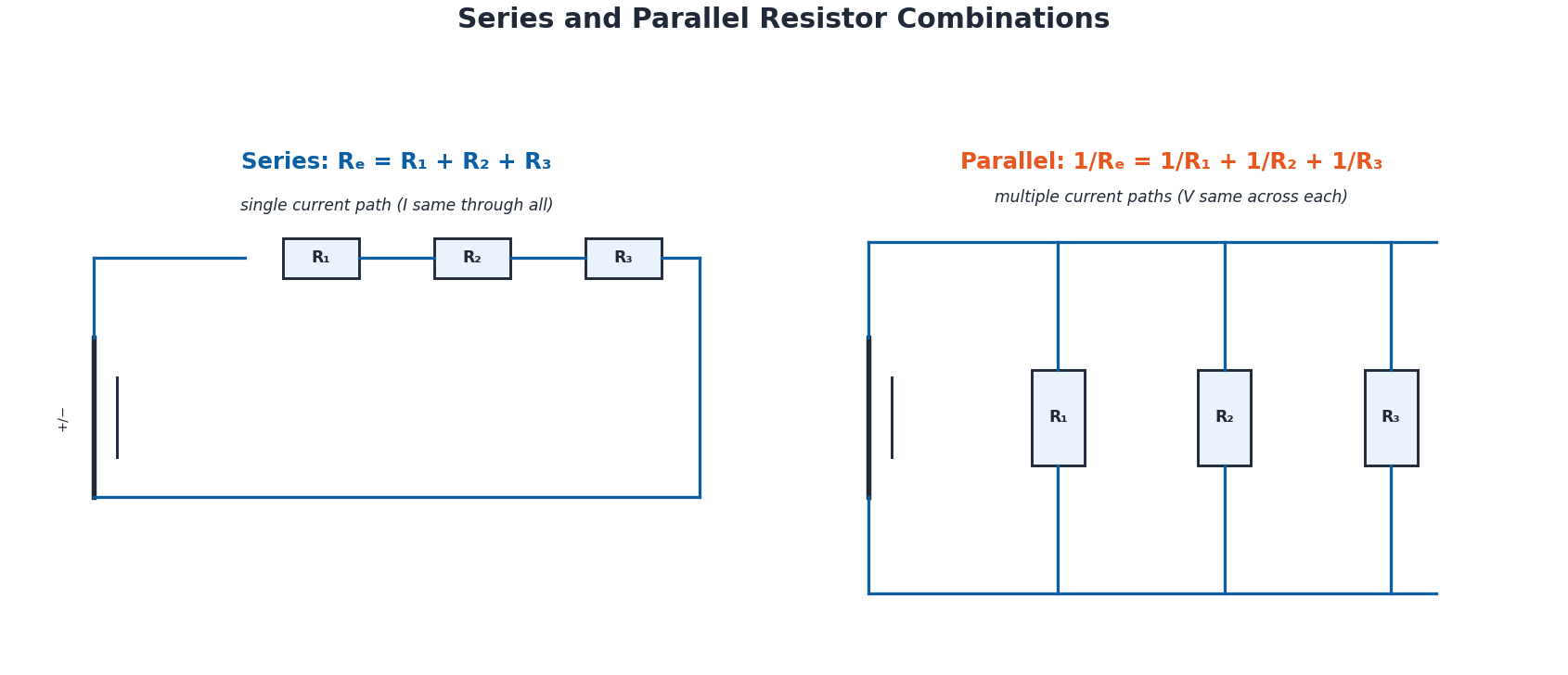
In a series combination, resistors are connected so there is only one path for current; the same current I flows through each resistor, and the total voltage is the sum of the voltages across each: V = V₁ + V₂ + V₃, which leads to the equivalent resistance being the simple sum Rₑ = R₁ + R₂ + R₃ — series resistance always increases the total resistance.
In a parallel combination, resistors provide multiple paths for current; the voltage across each resistor is the same (equal to the supply voltage), while the total current is the sum of the currents through each branch: I = I₁ + I₂ + I₃, leading to the reciprocal relationship 1/Rₑ = 1/R₁ + 1/R₂ + 1/R₃ — parallel resistance is always less than the smallest individual resistor. Worked Example: for 8 Ω and 24 Ω resistors in parallel across 30 V, 1/Rₑ = 1/8 + 1/24 = 4/24, so Rₑ = 6 Ω, and I = V/Rₑ = 30/6 = 5 A.
16.5 Electrical Resistivity and Temperature Effects
Resistance is the opposition a conductor offers to current flow; it is directly proportional to the conductor's length (L) and inversely proportional to its cross-sectional area (A): R = ρL/A, where ρ (rho) is the material's electrical resistivity, measured in ohm-metres (Ω m) — resistivity is the resistance of a 1 m³ sample of the material, and materials with high resistivity (like nichrome) are poor conductors, while those with low resistivity (like silver and copper) are excellent conductors. Worked Example: an aluminium wire of length 15 m, area 3×10⁻⁶ m², and resistivity 2.82×10⁻⁸ Ω m has resistance R = ρL/A = (2.82×10⁻⁸)(5×10⁶) = 0.141 Ω.
In most metals, resistance increases with temperature: heating increases atomic vibration, which impedes the movement of free electrons, so a hot filament (as in a light bulb) has higher resistance than a cold one. In semiconductors and insulators, however, resistance typically decreases as temperature rises, since more charge carriers (electrons or holes) are released, increasing conductivity — this is the working principle of the thermistor, a semiconductor-based resistor whose resistance drops as its temperature increases.
16.6 Potential Divider Circuits and Resistor Colour Codes
A potential (voltage) divider splits a supply voltage into smaller parts using two or more resistors connected in series: for resistors R₁ and R₂, the voltage across each is proportional to its share of the total resistance, following R₁/R₂ = V₁/V₂, with the total voltage Vₜₒₜₐₗ = V₁ + V₂; each individual voltage can be found directly as V₁ = Vₜₒₜₐₗ × R₁/(R₁+R₂) and V₂ = Vₜₒₜₐₗ × R₂/(R₁+R₂).
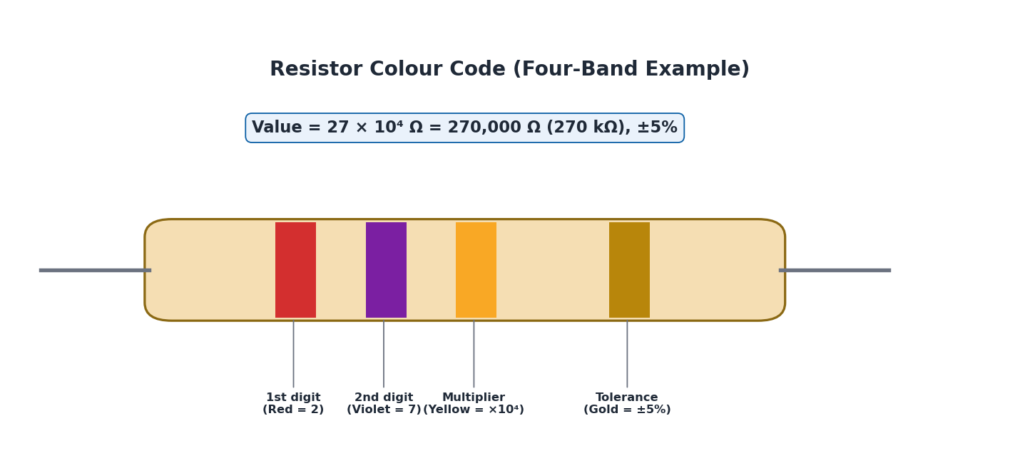
Resistor colour codes use coloured bands printed on a resistor to indicate its resistance value and tolerance (the allowed variation from the stated value) without needing a multimeter. In a standard four-band resistor, the first two bands give the first two digits, the third band gives the multiplier, and the fourth gives the tolerance; each colour corresponds to a specific digit/multiplier (black=0, brown=1, red=2, orange=3, yellow=4, green=5, blue=6, violet=7, grey=8, white=9), with gold (×10⁻², ±5%) and silver (×10⁻¹, ±10%) commonly used as tolerance bands. For example, red-violet-yellow-gold gives digits 2 and 7, multiplier ×10⁴, so resistance = 27 × 10⁴ = 270,000 Ω = 270 kΩ, with ±5% tolerance.
16.7 NTC Thermistors and Light-Dependent Resistors (LDRs)
A Negative Temperature Coefficient (NTC) thermistor is a resistor whose resistance decreases as temperature increases, because rising temperature gives charge carriers more energy to move freely through the semiconductor material, reducing resistance. NTC thermistors are used as input sensors in temperature-sensing circuits, such as electronic thermometers, temperature-monitoring circuits, temperature compensation, and overcurrent protection in power supplies (where resistance changes limit current as temperature rises).
A light-dependent resistor (LDR) is a resistor whose resistance decreases as light intensity increases, because absorbed light energy excites electrons in its photoconductive material, allowing more current to flow as light gets brighter. LDRs are used as input sensors in light-sensing circuits, such as automatic street lighting that turns on as it gets dark, and brightness sensors in cameras that automatically adjust exposure based on ambient light.
16.8 Electric Power, Joule's Law, and the Kilowatt-Hour
Electric power is the rate at which electrical energy is transferred or consumed: P = W/t, with SI unit watt (W), where 1 W = 1 J s⁻¹. Since V = IR, power can also be written as P = IV, and substituting further gives P = I²R and P = V²/R — three equivalent forms useful in different situations. Joule's law describes the heat produced by current flowing through resistance: H = I²Rt, or equivalently H = P × t (heat energy equals power multiplied by time); for example, a 100 W bulb running for 10 s produces H = 100 × 10 = 1000 J of heat.
Since household electrical energy use is very large, it is measured in kilowatt-hours (kWh) rather than joules: one kilowatt-hour is the energy delivered by a power of 1 kW over 1 hour (1 kWh = 1000 W × 3600 s = 3.6×10⁶ J = 3.6 MJ). Energy in kWh = (Power in watts × time in hours)/1000, and the electricity bill cost = number of units (kWh) consumed × cost per unit. Worked Example: a 100 W fan used 10 hours daily for 30 days consumes 0.1 kW × 10 h × 30 = 30 units; at Rs. 25 per unit, the monthly cost is 30 × 25 = Rs. 750. Choosing components with suitable power ratings is essential for circuit safety, reliability, and efficiency.
16.9 Household Circuits and Electrical Safety
Household appliances are connected in parallel, so each device (refrigerator, lights, TV) gets its own independent connection to the supply at the same constant voltage; this means one appliance can be switched off or a fuse can blow without cutting power to the rest of the house, making parallel wiring safer and more reliable than series wiring for domestic use. Common electrical hazards include damaged insulation (exposing live wires and risking shocks or short circuits), overheating cables (from carrying more current than designed for), and overloading sockets or extension leads (drawing excess current and risking fire).
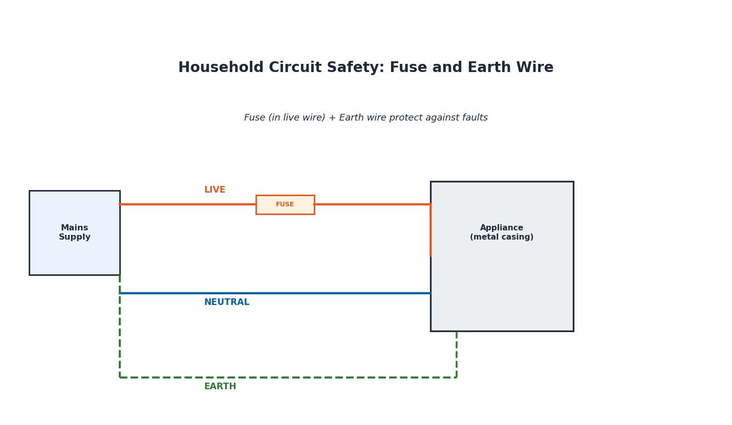
Fuses contain a thin wire that melts and breaks the circuit when current exceeds a safe level; trip switches (circuit breakers) automatically cut power when they detect a fault such as an overload or short circuit — both are connected into the live wire so the entire circuit is safely switched off when triggered. A typical mains circuit has three wires: the live (line) wire carrying current from the supply, the neutral wire completing the circuit, and the earth wire providing a safe, low-resistance path for fault current — if a live wire touches an earthed metal casing, current flows safely to ground rather than through a person touching the appliance, and this surge also trips the fuse/breaker. This is why appliance casings must be either non-conducting (double-insulated, as in many plastic-cased power tools) or properly earthed (as in metal-cased appliances like washing machines); electric shocks can cause burns and disrupt the body's own electrical signals, potentially causing cardiorespiratory failure, which is why these safety measures are so critical.
Important Definitions
Define electric current.
The amount of charge passing through a cross-section of a conductor per unit time: I = Q/t, measured in amperes (A), where 1 A = 1 C s⁻¹.
Define electromotive force (e.m.f.).
The electrical energy supplied by a source (like a battery) per unit charge as it moves around a complete circuit: E = W/Q, measured in volts.
Define potential difference (voltage).
The work done (energy converted) per unit charge as it passes through a component in a circuit: V = W/Q, measured in volts, where 1 V = 1 J C⁻¹.
State Ohm's law.
The current through a conductor is directly proportional to the potential difference across it, provided physical conditions remain constant: V = IR, where R is resistance in ohms (Ω).
Define resistivity.
A material property quantifying how strongly it resists current flow, defined via R = ρL/A; equal to the resistance of a 1 m³ sample of the material, measured in ohm-metres (Ω m).
What is an NTC thermistor?
A resistor made of semiconductor material whose resistance decreases as temperature increases, used as a temperature sensor.
What is a light-dependent resistor (LDR)?
A resistor whose resistance decreases as light intensity increases, used as a light sensor in circuits like automatic street lighting.
Define the kilowatt-hour (kWh).
The amount of electrical energy delivered by a power of one kilowatt over one hour; 1 kWh = 3.6 × 10⁶ J, the standard unit used for billing electricity consumption.
Key Formulas
| Topic | Formula |
|---|---|
| Electric current | I = Q / t |
| E.m.f. / Potential difference | E = W/Q, V = W/Q |
| Ohm's law | V = IR |
| Series resistance | Rₑ = R₁ + R₂ + R₃ |
| Parallel resistance | 1/Rₑ = 1/R₁ + 1/R₂ + 1/R₃ |
| Resistivity | R = ρL/A |
| Electric power | P = IV = I²R = V²/R |
| Heat energy (Joule's law) / kWh | H = I²Rt = Pt; Units (kWh) = (P in W × t in h)/1000 |
Diagrams
Series and Parallel Resistor Combinations: Three resistors connected in series (single current path) compared with three resistors connected in parallel (multiple current paths)
Resistor Colour Code: A four-band resistor labelled with colour bands for the first digit, second digit, multiplier, and tolerance
Household Circuit Safety: Fuse and Earth Wire: A simplified household circuit showing live, neutral, and earth wires, with a fuse in the live wire and an earthed appliance casing
Short Questions & Answers
How does an ammeter measure electric current?
An ammeter is connected in series with the component being tested, so the same current flows through it; it displays this current on an analog needle-and-scale or a digital numerical readout.
What is the main difference between direct current and alternating current?
Direct current (DC) flows in one direction only with constant voltage, as from a battery; alternating current (AC) periodically reverses direction, as supplied by power stations (50 Hz in Pakistan).
Define electromotive force (e.m.f.).
The electrical energy supplied by a source, such as a battery, per unit charge as it moves once around a complete circuit: E = W/Q, measured in volts.
State Ohm's law and define resistivity.
Ohm's law: current through a conductor is directly proportional to the potential difference across it at constant physical conditions, V = IR. Resistivity (ρ) is a material property quantifying resistance per unit length and area, via R = ρL/A, measured in ohm-metres.
What is the formula for calculating the equivalent resistance of resistors connected in series?
Rₑ = R₁ + R₂ + R₃ + … — the equivalent resistance is simply the sum of the individual resistances.
How does temperature affect the resistance of a conductor?
For most metallic conductors, resistance increases with temperature, since increased atomic vibration impedes electron movement; for semiconductors like thermistors, resistance instead decreases with temperature, as more charge carriers become available.
What is a kilowatt-hour, and why is it used?
A kilowatt-hour (kWh) is the energy delivered by 1 kW of power over 1 hour (3.6×10⁶ J); it is used because household electrical energy consumption is very large, and kWh gives a more practical, human-scale unit for billing.
Why must fuses and circuit breakers be connected into the live wire?
Connecting them in the live wire ensures that when a fault trips the fuse or breaker, the supply of current into the circuit is cut off completely and safely, rather than leaving the appliance connected to a live but unswitched wire.
Long Questions & Answers
Explain the concept of electric current, its relation to the movement of charges, and how it is measured in a circuit.
Electric current is the flow of electric charge through a conductor, caused by the directed movement of free electrons (in metals) under the influence of an applied electric field; without an applied field, these free electrons move randomly in all directions, but once a voltage is applied, they drift in a specific direction, constituting a current. Quantitatively, current is defined as the amount of charge Q passing through a cross-section of a conductor per unit time t: I = Q/t, measured in amperes (A), where one ampere corresponds to one coulomb of charge flowing per second. Historically, before electrons were discovered, current was assumed to be due to the flow of positive charge from a source's positive terminal to its negative terminal — this is called conventional current, and remains the standard convention used in circuit diagrams and analysis today, even though we now know that in metals it is actually negatively charged electrons flowing in the opposite direction (from negative to positive terminal) that carry the current; the movement of electrons in one direction is electrically equivalent to the movement of positive charge in the other. Current is measured using an ammeter, which must always be connected in series with the component whose current is being measured, so that the full current being measured actually flows through the meter itself; ammeters are available as analog types (using a needle and scale, useful for simple visual demonstrations) or digital types (giving a precise numerical readout), and both come with multiple selectable ranges to accurately measure currents of different magnitudes without damaging the instrument.
Define electromotive force (e.m.f.) and potential difference, and explain how a battery creates potential difference and how e.m.f. maintains current flow.
Electromotive force (e.m.f.) is the electrical energy supplied by a source, such as a battery, per unit charge as that charge is driven once around a complete circuit, expressed as E = W/Q, where W is the energy converted from a non-electrical form (chemical, thermal, or mechanical) into electrical form, and Q is the charge moved; e.m.f. is measured in volts, where one volt equals one joule of energy per coulomb of charge. Potential difference (p.d., also called voltage) is closely related but distinct: it is the energy used (converted from electrical to another form, such as heat or light) per unit charge as that charge passes through a specific component in the circuit, expressed using the same basic relationship V = W/Q. Inside a battery, a chemical reaction causes electrons to build up at the negative terminal while creating a shortage of electrons at the positive terminal; this imbalance of charge between the two terminals is exactly what creates a potential difference across the battery. Once the battery is connected into a complete circuit, this potential difference drives current: positive charge conventionally flows from the higher-potential (positive) terminal, through the external circuit and any connected components, to the lower-potential (negative) terminal. However, for the current to continue flowing continuously rather than stopping once the charge reaches the negative terminal, the battery's ongoing chemical reaction must continuously do work to push charge back from the negative terminal to the positive terminal internally, ready to flow around the circuit again — this internal work, supplying the energy that sustains continuous current flow against the resistance of the circuit, is precisely the role of the e.m.f.: without it, any initial current would quickly die out as the charge imbalance driving it was neutralized.
State and explain Ohm's law, and describe how resistors combine in series and in parallel, including the formulas for total resistance in each case.
Ohm's law, established experimentally by Georg Simon Ohm in 1826, states that the current flowing through a conductor is directly proportional to the potential difference applied across its ends, provided the conductor's physical conditions — such as its dimensions and temperature — remain unchanged. This relationship is expressed as V = IR, where R, the resistance, is the constant of proportionality linking voltage and current for that particular conductor, measured in ohms (Ω); a higher resistance means that a larger voltage is needed to drive the same current through the conductor, since resistance directly opposes and limits the flow of charge. When several resistors are combined in a circuit, how they are connected determines the circuit's total (equivalent) resistance and behaviour. In a series combination, resistors are connected end-to-end so there is only a single path for current to follow; because the same current flows through each resistor, but each individually adds its own voltage drop, the total voltage across the combination is the sum of the individual voltage drops, which leads directly to the equivalent resistance formula Rₑ = R₁ + R₂ + R₃ — meaning series resistance always adds up, making the total resistance greater than any single resistor in the chain. In a parallel combination, resistors are instead connected so that multiple separate paths exist for current to flow between the same two points; because each resistor experiences the identical voltage (the full supply voltage), but the current divides itself among the available paths according to each resistor's individual resistance, the total current is the sum of the branch currents, which leads to the reciprocal formula 1/Rₑ = 1/R₁ + 1/R₂ + 1/R₃ — meaning parallel resistance combinations always result in a total resistance smaller than the smallest individual resistor, since adding more parallel paths only makes it easier, not harder, for current to flow overall.
Discuss the safety features of household electrical circuits, including the role of the earth wire, fuses, and trip switches, and explain why domestic supplies are connected in parallel.
Household electrical circuits are deliberately designed with several layers of protection to prevent electric shocks, fires, and damage to property. A typical mains circuit consists of three wires: the live (or line) wire, which carries current from the power supply at high potential; the neutral wire, which completes the circuit and returns current at close to zero potential; and the earth wire, a dedicated safety conductor connected to the ground. The earth wire's purpose becomes critical if a fault develops — for instance, if damaged insulation allows the live wire to accidentally touch an appliance's metal casing. Without an earth connection, that casing would become live at full mains voltage, posing a serious shock hazard to anyone who touches it; with a properly earthed casing, however, the fault current instead flows harmlessly through the low-resistance earth wire into the ground, and this sudden surge of current is exactly what triggers a fuse to melt or a trip switch (circuit breaker) to activate, cutting off the power automatically. This is precisely why an appliance's outer casing must be either non-conducting (double-insulated, typically using plastic casings, as in many power tools, which cannot become live even without earthing) or properly earthed (as in metal-cased appliances like washing machines and refrigerators) — one of these two protections must always be present. Fuses and trip switches are both deliberately connected into the live wire of a circuit, rather than the neutral wire, because this ensures that when they activate, the incoming supply of current is fully interrupted, leaving the appliance completely disconnected from the live potential rather than merely from the return path. Finally, domestic electrical supplies are connected in parallel — rather than in series — specifically for safety and convenience: in a parallel arrangement, every appliance receives its own independent connection at the same full supply voltage, meaning that any single appliance can be switched off, unplugged, or fail (blowing its own fuse) without disrupting the voltage or operation of any other appliance in the home; in a series arrangement, by contrast, one broken or switched-off appliance would interrupt the single shared current path and cut off power to every other device in the same circuit, which would be both highly impractical and considerably more dangerous.
Multiple Choice Questions (MCQs)
The direction of conventional current is: (A) from negative to positive terminal (B) from positive to negative terminal (C) in both directions at the same time (D) it does not have a fixed direction
Correct answer: (B) from positive to negative terminal. Conventional current is defined as flowing from the positive terminal, through the external circuit, to the negative terminal.
What type of electric current flows in one direction only? (A) Alternating current (B) Direct current (C) Induced current (D) None of these
Correct answer: (B) Direct current. Direct current (DC) flows in a single, constant direction, unlike alternating current, which periodically reverses.
The device used to measure electric current is: (A) voltmeter (B) ammeter (C) ohmmeter (D) wattmeter
Correct answer: (B) ammeter. An ammeter measures electric current and is connected in series with the circuit component being tested.
What is the function of an e.m.f. source in a circuit? (A) To reduce resistance in the circuit (B) To provide energy to drive charges through the circuit (C) To store electrical energy for later use (D) To convert electrical energy into mechanical energy
Correct answer: (B) To provide energy to drive charges through the circuit. An e.m.f. source supplies the energy needed to keep charges moving continuously around a complete circuit.
The relationship between voltage, current, and resistance is: (A) V = IR (B) V = I/R (C) V = I²R (D) V = R/I
Correct answer: (A) V = IR. Ohm's law states V = IR, relating voltage, current, and resistance directly.
What happens to the resistance of a metal conductor when its temperature increases? (A) It decreases (B) It remains constant (C) It increases (D) It becomes zero
Correct answer: (C) It increases. In most metals, increased temperature increases atomic vibration, impeding electron flow and raising resistance.
One kilowatt-hour (1 kWh) of energy is equal to: (A) 1000 J (B) 3600 J (C) 3.6 × 10⁶ J (D) 1 J
Correct answer: (C) 3.6 × 10⁶ J. 1 kWh = 1000 W × 3600 s = 3.6 × 10⁶ J.
A resistor with colour bands Red-Violet-Yellow-Gold has a resistance of: (A) 27 Ω (B) 2,700 Ω (C) 270,000 Ω (D) 27,000,000 Ω
Correct answer: (C) 270,000 Ω. Red=2, Violet=7, Yellow multiplier=10⁴: 27 × 10⁴ = 270,000 Ω (270 kΩ), with gold ±5% tolerance.
A Negative Temperature Coefficient (NTC) thermistor's resistance: (A) increases as temperature increases (B) decreases as temperature increases (C) stays constant with temperature (D) becomes infinite at high temperature
Correct answer: (B) decreases as temperature increases. An NTC thermistor's resistance decreases as temperature rises, since more charge carriers become available in its semiconductor material.
Electric power can be correctly expressed as: (A) P = I/V (B) P = IV (C) P = V/I² (D) P = I/R
Correct answer: (B) P = IV. Electric power P = IV (current × voltage), equivalent to P = I²R and P = V²/R using Ohm's law.
Quick Revision Summary
- Current: I = Q/t (amperes); conventional current (+ to −) vs electronic current (electron flow, − to +)
- DC: one direction, constant; AC: reverses periodically (50 Hz in Pakistan), better for long-distance transmission
- E.m.f. E = W/Q (energy supplied by source); p.d. V = W/Q (energy used by component) — both in volts
- Series e.m.f.: Eₜₒₜₐₗ = E₁+E₂+…; Parallel identical e.m.f.: Eₜₒₜₐₗ = E (single source value, more available current)
- Ohm's law: V = IR. Series: Rₑ=R₁+R₂+R₃ (current same, voltage adds). Parallel: 1/Rₑ=1/R₁+1/R₂+1/R₃ (voltage same, current adds)
- Resistivity: R = ρL/A; metals: resistance ↑ with temperature; semiconductors/thermistors: resistance ↓ with temperature
- Potential divider: R₁/R₂ = V₁/V₂; resistor colour code: digit-digit-multiplier-tolerance bands
- NTC thermistor (temperature sensor) and LDR (light sensor): both show falling resistance with rising stimulus
- Power: P=IV=I²R=V²/R; Heat/energy: H=Pt; kWh = (P in W × t in h)/1000; cost = units × price/unit
- Household circuits: parallel wiring (independent appliances); live/neutral/earth wires; fuse & trip switch in live wire; earthing/double-insulation prevents shock
Exam Tips
- Always state ammeters connect in SERIES (low resistance) and voltmeters connect in PARALLEL (high resistance) — a frequently tested distinction
- For series vs parallel resistor problems, remember: series ADDS resistances directly; parallel uses RECIPROCALS and always gives a smaller total
- Convert all values to base SI units (Ω, m, m², A, V) before substituting into resistivity or power formulas
- For kWh/billing problems, always convert watts to kilowatts (divide by 1000) before multiplying by hours
- Remember NTC thermistors and LDRs both work the same way conceptually: resistance falls as the relevant stimulus (temperature or light) rises
- For household safety questions, always mention all three: fuse/trip switch (in the live wire), earth wire, and double-insulation/earthing of casings