This chapter covers Electromagnetic Induction from the 2nd Year (FSc Part-II) Physics syllabus of the Punjab Curriculum and Textbook Board (PTB/PCTB). It studies induced EMF, motional EMF, Faraday’s law, Lenz’s law, mutual and self induction, energy stored in an inductor, the A.C. and D.C. generators, the D.C. motor, back EMF and the transformer. These notes are prepared by freebooks.pk.
Electromagnetic induction is the reverse of electromagnetism: a changing magnetic field produces an electric current. This single idea gives us generators, transformers and the entire electrical power supply.
Learning Objectives
- Explain how a changing magnetic flux induces an EMF.
- Derive and use the expression for motional EMF.
- State Faraday’s law and Lenz’s law.
- Explain mutual and self induction and energy stored in an inductor.
- Describe the A.C. and D.C. generators and the D.C. motor with back EMF.
- Explain the working of a transformer.
Key Concepts
Induced EMF and Induced Current
Faraday found that whenever the magnetic flux linking a coil changes, an electromotive force is set up in the coil, and if the circuit is closed an induced current flows. The change of flux can be produced by moving a magnet towards or away from the coil, by moving the coil, or by changing the current in a nearby coil. No EMF is induced while the flux is steady; an EMF appears only while the flux is changing. This is the phenomenon of electromagnetic induction.
Motional EMF
When a straight conductor of length L moves with speed v at right angles to a magnetic field of flux density B, the free charges in it experience a force and an EMF is induced across its ends, given by EMF = v B L. This motional EMF arises because the moving conductor sweeps through magnetic flux; it is the basis of the electric generator, in which conductors are moved through a magnetic field to generate electricity.
Faraday’s Law
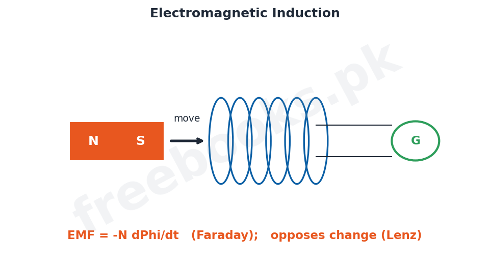
Faraday’s law of electromagnetic induction states that the magnitude of the induced EMF is equal to the rate of change of magnetic flux linkage, EMF = -N (delta Phi / delta t), where N is the number of turns and Phi the flux through each turn. The faster the flux changes, or the more turns the coil has, the greater the induced EMF. The minus sign indicates the direction of the induced EMF, which is given by Lenz’s law.
Lenz’s Law
Lenz’s law states that the direction of the induced current is always such as to oppose the change that produces it. For example, when a north pole is pushed towards a coil the induced current flows so as to make the near face of the coil a north pole, which repels the approaching magnet and opposes its motion. Lenz’s law is a direct consequence of the conservation of energy, because the work done against this opposition is what appears as electrical energy.
Mutual and Self Induction
Mutual induction occurs when a changing current in one coil induces an EMF in a neighbouring coil because the changing flux of the first coil links the second; this is the principle of the transformer. Self induction occurs when a changing current in a coil induces an EMF in the same coil that opposes the change of current. The property of a coil to oppose changes in current is called its inductance L, measured in henries; a coil with inductance is called an inductor.
Energy Stored in an Inductor
Because an inductor opposes changes in the current through it, work has to be done to establish a current, and this energy is stored in the magnetic field of the inductor. The energy stored is E = (1/2) L I^2, where L is the inductance and I the final current. This stored magnetic energy is released when the current is switched off, which is why breaking an inductive circuit can produce a spark.
Generators and the D.C. Motor
A generator converts mechanical energy into electrical energy using electromagnetic induction: a coil is rotated in a magnetic field so that the flux through it changes continuously, inducing an EMF. In the A.C. generator the coil is connected to slip rings and the output is alternating; in the D.C. generator a split-ring commutator reverses the connections each half turn so that the output is direct. The D.C. motor is the reverse device: it uses the force on a current-carrying coil in a magnetic field to convert electrical energy into mechanical rotation.
Back EMF and the Transformer
As the coil of a running motor rotates it also acts as a generator and produces an EMF that opposes the applied voltage; this is called the back EMF, and it limits the current drawn by the motor. The transformer is a device that changes the size of an alternating voltage using mutual induction between two coils wound on a common iron core. The voltages are related to the numbers of turns by Vs/Vp = Ns/Np: a step-up transformer has more turns on the secondary and raises the voltage, while a step-down transformer has fewer and lowers it. Transformers make the efficient transmission of electrical power possible.
Important Definitions
Electromagnetic induction
The production of an EMF by a changing magnetic flux.
Motional EMF
The EMF induced in a conductor moving through a field, EMF = v B L.
Faraday’s law
Induced EMF = rate of change of flux linkage, EMF = -N delta Phi/delta t.
Lenz’s law
The induced current opposes the change that produces it.
Mutual induction
EMF induced in one coil by a changing current in a neighbouring coil.
Self induction
EMF induced in a coil by a change of its own current.
Inductance
The property of a coil to oppose changes in current, unit henry.
Transformer
A device that changes an alternating voltage using mutual induction.
Formulas & Rules
| Item | Fact |
|---|---|
| Motional EMF | EMF = v B L |
| Faraday’s law | EMF = -N (delta Phi / delta t) |
| Energy in an inductor | E = (1/2) L I^2 |
| Transformer relation | Vs/Vp = Ns/Np |
| Ideal transformer power | Vp Ip = Vs Is |
Diagrams & Illustrations
Electromagnetic induction: a bar magnet moved towards a coil connected to a galvanometer, inducing a current whose direction opposes the change (Faraday’s and Lenz’s laws).
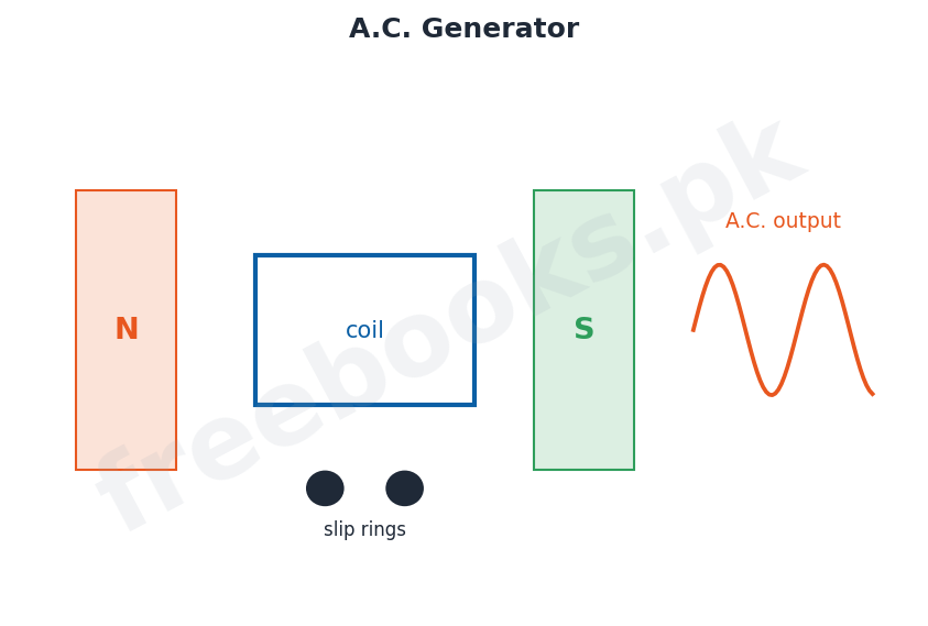
A.C. generator: a coil rotating between magnetic poles with slip rings, producing an alternating output voltage.
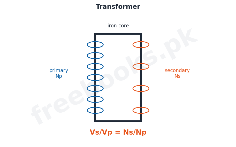
Transformer: primary and secondary coils wound on a common iron core, with Vs/Vp = Ns/Np.
Solved Examples & Numericals
Motional EMF
A rod 0.5 m long moves at 4 m/s perpendicular to a 0.2 T field. EMF = v B L = 4 x 0.2 x 0.5 = 0.4 V.
Faraday’s law
A coil of 100 turns has its flux changing by 2×10^-3 Wb in 0.1 s. EMF = N delta Phi/delta t = 100 x 2×10^-3 / 0.1 = 2 V.
Energy in an inductor
An inductor of 0.5 H carries 2 A. Energy stored = (1/2) L I^2 = 0.5 x 0.5 x 4 = 1 J.
Transformer
A transformer has Np = 100, Ns = 500 and Vp = 220 V. Then Vs = Vp x Ns/Np = 220 x 5 = 1100 V (step-up).
Short Questions & Answers
What is electromagnetic induction?
The production of an EMF (and current, if the circuit is closed) by a changing magnetic flux.
Write the expression for motional EMF.
EMF = v B L for a conductor of length L moving at speed v perpendicular to a field B.
State Faraday’s law.
The induced EMF equals the rate of change of magnetic flux linkage, EMF = -N delta Phi/delta t.
State Lenz’s law.
The induced current always flows in a direction that opposes the change producing it (conservation of energy).
What is self induction?
The induction of an EMF in a coil by a change of its own current, opposing that change.
Write the transformer turns relation.
Vs/Vp = Ns/Np, relating the voltages to the numbers of turns.
Long Questions & Answers
Q1: State Faraday’s law and Lenz’s law and explain how they describe electromagnetic induction.
Electromagnetic induction is the production of an electromotive force whenever the magnetic flux linking a circuit changes. Faraday’s law gives the size of this induced EMF: it states that the magnitude of the induced EMF is equal to the rate of change of the magnetic flux linkage of the coil, EMF = -N (delta Phi / delta t), where N is the number of turns in the coil and Phi is the flux threading each turn. Thus the induced EMF is large when the flux changes rapidly and when the coil has many turns, and it is zero when the flux is steady. Lenz’s law gives the direction of the induced effect: it states that the induced current always flows in such a direction as to oppose the very change that is producing it, which is the reason for the minus sign in Faraday’s law. For instance, when the north pole of a magnet is pushed towards a coil, the induced current makes the near face of the coil into a north pole so as to repel the magnet and oppose its approach; if the magnet is pulled away, the induced current reverses so as to attract it and oppose its withdrawal. Lenz’s law is really a statement of the conservation of energy, because the mechanical work done against this opposition is exactly what is converted into electrical energy in the coil.
Q2: Describe the construction and working of an A.C. generator.
An alternating-current generator converts mechanical energy into electrical energy by electromagnetic induction. It consists of a coil of many turns of wire, called the armature, which is free to rotate in the magnetic field produced by a permanent magnet or electromagnet. The two ends of the coil are connected to two separate slip rings, against which carbon brushes press to carry the current to the external circuit. When the coil is rotated (by a turbine, engine or other prime mover), the magnetic flux passing through it changes continuously: as the coil turns, the flux linkage rises and falls, so by Faraday’s law an EMF is induced in it. During one half of each revolution the flux is increasing and the induced EMF acts one way, and during the other half the flux is decreasing and the EMF reverses, so the output is an alternating voltage that rises and falls in the shape of a sine curve, reversing its direction twice in every complete rotation. The slip rings keep each end of the coil permanently connected to the same brush, so the alternating nature of the current is delivered unchanged to the circuit. This is the principle used in the huge generators of power stations that supply mains electricity.
Q3: Explain the working of a transformer, how it changes voltage, and why it is used in power transmission.
A transformer is a device that increases or decreases the size of an alternating voltage by means of mutual induction. It consists of two coils, a primary and a secondary, wound on a common core of soft iron. When an alternating voltage is applied to the primary coil, it drives an alternating current that sets up a continually changing magnetic flux in the iron core; the core guides almost all of this flux through the secondary coil, so a changing flux links the secondary and, by Faraday’s law, induces an alternating EMF in it. Because the same flux links each turn of both coils, the induced voltages are proportional to the numbers of turns, giving the relation Vs/Vp = Ns/Np, where the subscripts p and s refer to the primary and secondary. If the secondary has more turns than the primary it is a step-up transformer and raises the voltage; if it has fewer, it is a step-down transformer and lowers the voltage. In an ideal transformer no energy is lost, so the power on the two sides is equal, Vp Ip = Vs Is, which means that stepping the voltage up steps the current down and vice versa. Transformers are essential in the transmission of electrical power: electricity is generated at moderate voltage, stepped up to a very high voltage for transmission over long distances (which greatly reduces the current and hence the energy wasted as heat in the cables), and then stepped down again to safe values for use in homes and factories.
MCQs with Answers
An EMF is induced in a coil only when the flux is: (a) steady (b) zero (c) changing (d) maximum
Correct Answer: (c) changing.
Motional EMF is: (a) v B L (b) B L/v (c) v/BL (d) B/vL
Correct Answer: (a) v B L.
Faraday’s law gives EMF equal to the rate of change of: (a) current (b) charge (c) flux linkage (d) resistance
Correct Answer: (c) flux linkage.
Lenz’s law is a consequence of conservation of: (a) charge (b) energy (c) mass (d) momentum
Correct Answer: (b) energy.
The unit of inductance is the: (a) tesla (b) henry (c) weber (d) farad
Correct Answer: (b) henry.
Energy stored in an inductor is: (a) (1/2) L I^2 (b) L I (c) (1/2) L I (d) L I^2
Correct Answer: (a) (1/2) L I^2.
An A.C. generator uses: (a) a commutator (b) slip rings (c) a battery (d) a diode
Correct Answer: (b) slip rings.
A split-ring commutator is used in a: (a) A.C. generator (b) D.C. generator (c) transformer (d) voltmeter
Correct Answer: (b) D.C. generator.
The transformer works on: (a) self induction only (b) mutual induction (c) electrostatics (d) resistance
Correct Answer: (b) mutual induction.
A step-up transformer has more turns on the: (a) primary (b) secondary (c) core (d) brush
Correct Answer: (b) secondary.
Quick Revision Summary
- Induction: changing flux induces EMF (and current if circuit closed).
- Motional EMF = v B L; Faraday: EMF = -N delta Phi/delta t.
- Lenz’s law: induced current opposes the change (energy conservation).
- Mutual/self induction; inductance L (henry); energy = (1/2) L I^2.
- A.C. generator (slip rings) vs D.C. generator (commutator); motor has back EMF.
- Transformer: Vs/Vp = Ns/Np; Vp Ip = Vs Is; used in power transmission. Notes by freebooks.pk.
Exam Tips
- Stress that only a changing flux induces an EMF.
- Learn EMF = v B L and Faraday’s law EMF = -N delta Phi/delta t.
- State Lenz’s law and link it to energy conservation.
- Remember energy in an inductor = (1/2) L I^2.
- Distinguish A.C. (slip rings) and D.C. (commutator) generators.
- Memorise the transformer turns and power relations.