This chapter covers Alternating Current from the 2nd Year (FSc Part-II) Physics syllabus of the Punjab Curriculum and Textbook Board (PTB/PCTB). It studies alternating current and its peak and rms values, A.C. through a resistor, capacitor and inductor, reactance and impedance, R-C and R-L circuits, power in A.C. circuits, series and parallel resonance, the choke and electromagnetic waves with their transmission and modulation. These notes are prepared by freebooks.pk.
Alternating current reverses direction many times each second and is the form in which electricity is generated and supplied. Understanding how it behaves in resistors, capacitors and inductors explains radios, tuning circuits and the whole of A.C. technology.
Learning Objectives
- Define alternating current and its peak and rms values.
- Describe A.C. through a resistor, a capacitor and an inductor.
- Define reactance and impedance.
- Analyse R-C and R-L series circuits and power in A.C. circuits.
- Explain series and parallel resonance.
- Describe electromagnetic waves and modulation.
Key Concepts
Alternating Current and Its Values
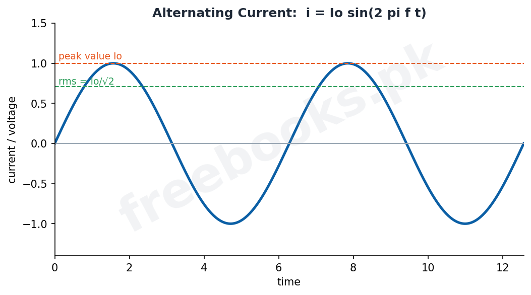
An alternating current (A.C.) is one that reverses its direction periodically, usually varying sinusoidally with time as i = Io sin(2 pi f t), where Io is the peak (maximum) value and f the frequency. The instantaneous value changes from moment to moment. Because the current is sometimes positive and sometimes negative, its average over a cycle is zero, so its effective size is described by the root-mean-square (rms) value, Irms = Io / sqrt 2, which is the steady direct current that would produce the same heating effect. Mains voltage quoted as 220 V is an rms value.
A.C. Through a Resistor
When an alternating voltage is applied across a pure resistor, the current is in phase with the voltage, meaning both reach their peaks and zeros at the same instants. Ohm’s law holds at every instant, so the peak current is Io = Vo / R and the rms current is Vrms / R. A resistor dissipates energy as heat in an A.C. circuit just as it does with direct current.
A.C. Through a Capacitor
When an alternating voltage is applied across a capacitor, the current leads the voltage by 90 degrees (a quarter cycle), because the capacitor must charge before a voltage appears across it. The capacitor opposes the flow of A.C. through its capacitive reactance, Xc = 1 / (2 pi f C), which is measured in ohms. The reactance is large at low frequency (so a capacitor blocks direct current, for which f = 0) and small at high frequency.
A.C. Through an Inductor
When an alternating voltage is applied across a pure inductor, the current lags the voltage by 90 degrees, because the induced back EMF opposes changes in current. The inductor opposes A.C. through its inductive reactance, XL = 2 pi f L, also measured in ohms. Unlike the capacitor, the inductive reactance is small at low frequency and large at high frequency, so an inductor readily passes direct current but impedes high-frequency A.C.
Impedance and R-C, R-L Circuits
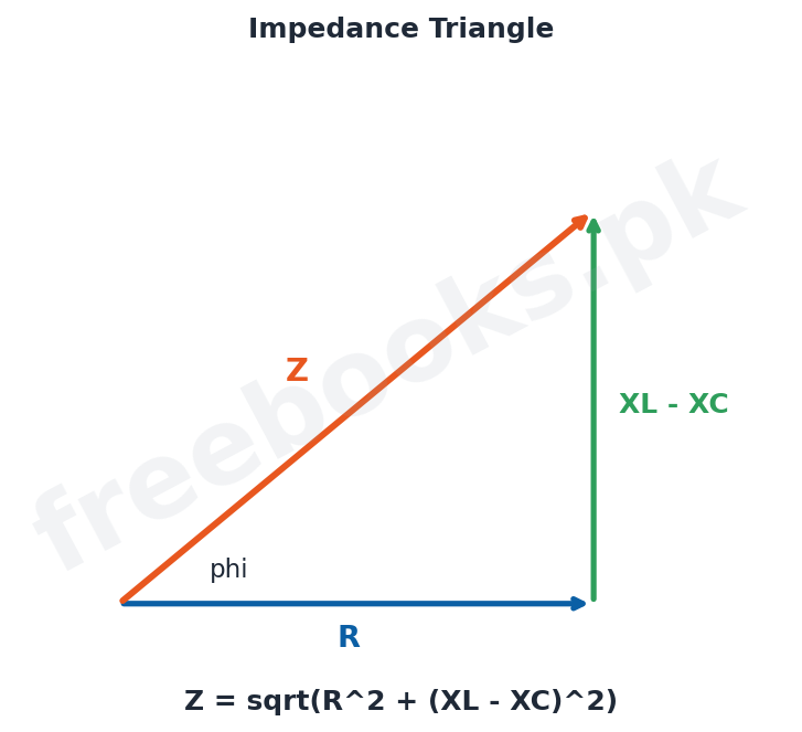
In a circuit containing resistance and reactance together, the combined opposition to alternating current is called the impedance Z, measured in ohms, and the current is Irms = Vrms / Z. For a series circuit containing resistance R, inductive reactance XL and capacitive reactance XC, the impedance is Z = sqrt(R^2 + (XL – XC)^2). In an R-L or R-C circuit the current and voltage are out of phase by an angle phi given by the impedance triangle, where tan phi = (XL – XC)/R.
Power in A.C. Circuits
In an A.C. circuit the average power delivered is P = Vrms Irms cos phi, where cos phi is called the power factor and phi is the phase angle between current and voltage. In a pure resistor phi = 0 and cos phi = 1, so all the power is dissipated; in a pure capacitor or inductor phi = 90 degrees and cos phi = 0, so on average no power is consumed. Real circuits lie between these extremes, and a good power factor is desirable for efficient use of electrical energy.
Resonance
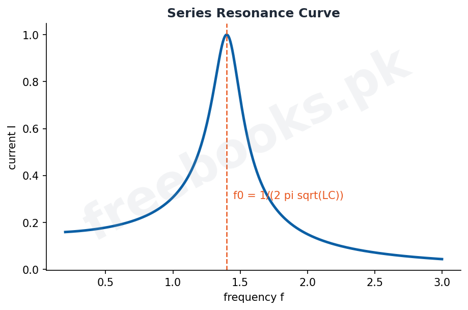
In a series R-L-C circuit the inductive and capacitive reactances cancel at a particular frequency called the resonant frequency, f0 = 1 / (2 pi sqrt(L C)). At resonance the impedance is minimum (equal to R alone) and the current is maximum. A parallel resonance circuit behaves in the opposite way, offering maximum impedance and minimum current at resonance. Resonance circuits are used to tune radios and televisions to a chosen station by selecting the frequency at which the response is greatest.
Electromagnetic Waves and Modulation
Accelerating charges, such as those in an aerial carrying a high-frequency alternating current, radiate electromagnetic waves, which consist of oscillating electric and magnetic fields travelling through space at the speed of light and needing no medium. To carry information, a low-frequency signal (such as speech or music) is combined with a high-frequency carrier wave in a process called modulation: in amplitude modulation (AM) the amplitude of the carrier is varied in step with the signal, while in frequency modulation (FM) its frequency is varied. The modulated wave is transmitted from an aerial, received by another aerial and then demodulated to recover the original signal.
Important Definitions
Alternating current
A current that reverses direction periodically, i = Io sin(2 pi f t).
Peak value
The maximum value of an alternating current or voltage, Io.
Rms value
The effective value, Irms = Io / sqrt 2, giving the same heating as a D.C.
Capacitive reactance
The opposition of a capacitor to A.C., Xc = 1/(2 pi f C).
Inductive reactance
The opposition of an inductor to A.C., XL = 2 pi f L.
Impedance
The total opposition to A.C., Z = sqrt(R^2 + (XL – XC)^2).
Power factor
cos phi, the cosine of the phase angle between current and voltage.
Resonant frequency
The frequency at which XL = XC, f0 = 1/(2 pi sqrt(L C)).
Formulas & Rules
| Item | Fact |
|---|---|
| Instantaneous current | i = Io sin(2 pi f t) |
| Rms value | Irms = Io / sqrt 2 |
| Capacitive reactance | Xc = 1 / (2 pi f C) |
| Inductive reactance | XL = 2 pi f L |
| Impedance | Z = sqrt(R^2 + (XL – XC)^2) |
| Power in A.C. | P = Vrms Irms cos phi |
| Resonant frequency | f0 = 1 / (2 pi sqrt(L C)) |
Diagrams & Illustrations
Alternating current: a sine graph of alternating current against time, marking the peak value Io and the rms value Io/sqrt 2.
Impedance triangle: an impedance triangle with resistance R, net reactance (XL – XC) and impedance Z, showing the phase angle phi.
Series resonance curve: a graph of current against frequency for a series R-L-C circuit, peaking at the resonant frequency f0.
Solved Examples & Numericals
Rms value
An alternating current has a peak value of 10 A. Its rms value is Irms = Io/sqrt 2 = 10/1.414 = 7.07 A.
Capacitive reactance
A 10 microfarad capacitor is used at 50 Hz. Xc = 1/(2 pi f C) = 1/(2 pi x 50 x 10×10^-6) = 318 ohm.
Inductive reactance
A 0.2 H inductor is used at 50 Hz. XL = 2 pi f L = 2 pi x 50 x 0.2 = 63 ohm.
Impedance
A series circuit has R = 30 ohm, XL = 80 ohm, XC = 40 ohm. Z = sqrt(30^2 + (80-40)^2) = sqrt(900 + 1600) = 50 ohm.
Resonant frequency
For L = 0.1 H and C = 10 microfarad, f0 = 1/(2 pi sqrt(0.1 x 10×10^-6)) = 1/(2 pi x 10^-3) = 159 Hz.
Short Questions & Answers
What is alternating current?
A current that periodically reverses its direction, usually varying sinusoidally, i = Io sin(2 pi f t).
Define the rms value of A.C.
The steady direct current that would produce the same heating effect, Irms = Io/sqrt 2.
Write the capacitive reactance.
Xc = 1/(2 pi f C); it is large at low frequency and small at high frequency.
Write the inductive reactance.
XL = 2 pi f L; it is small at low frequency and large at high frequency.
What is the power factor?
cos phi, the cosine of the phase angle between current and voltage; it determines the power consumed.
Write the resonant frequency of a series circuit.
f0 = 1/(2 pi sqrt(L C)), where XL = XC and the current is maximum.
Long Questions & Answers
Q1: Describe the behaviour of alternating current through a resistor, a capacitor and an inductor.
The way an alternating current behaves depends on the circuit element it passes through. In a pure resistor the current is exactly in phase with the applied voltage, so both reach their maximum and zero values at the same instants; Ohm’s law holds at every moment and the resistor simply dissipates energy as heat, with peak current Io = Vo/R. In a capacitor the situation is different: the current leads the voltage by a quarter of a cycle (90 degrees), because current must flow to charge the plates before a voltage can build up across them. A capacitor opposes alternating current through its capacitive reactance Xc = 1/(2 pi f C), which is large at low frequencies and becomes infinite for direct current (f = 0), so a capacitor blocks D.C. but passes high-frequency A.C. In a pure inductor the current lags the voltage by a quarter cycle, because the self-induced back EMF opposes any change in the current; the inductor opposes A.C. through its inductive reactance XL = 2 pi f L, which is small at low frequencies and large at high frequencies, so an inductor passes D.C. easily but chokes off high-frequency A.C. These phase relationships and reactances are the key to understanding all A.C. circuits.
Q2: Define impedance and power in an A.C. circuit and explain the power factor.
When a circuit contains resistance together with capacitance and/or inductance, the total opposition it offers to alternating current is called the impedance Z, measured in ohms, and the rms current is given by Irms = Vrms/Z. For a series circuit the impedance combines the resistance and the net reactance at right angles, Z = sqrt(R^2 + (XL – XC)^2), and the current and voltage are out of step by a phase angle phi such that tan phi = (XL – XC)/R; this relationship is conveniently shown by the impedance triangle. The average power actually consumed in the circuit is not simply Vrms Irms, but P = Vrms Irms cos phi, where the factor cos phi is called the power factor. Its value depends on the phase angle: in a purely resistive circuit phi = 0 and cos phi = 1, so the whole of the apparent power is dissipated as heat; in a purely inductive or purely capacitive circuit phi = 90 degrees and cos phi = 0, so on average no power is consumed even though a current flows, because energy is alternately stored and returned by the reactive element. Practical circuits lie between these extremes, and electrical engineers aim for a power factor close to one so that electrical energy is used efficiently and cables do not have to carry unnecessarily large currents.
Q3: Explain resonance in a series R-L-C circuit and describe electromagnetic waves and modulation.
In a series circuit containing resistance, inductance and capacitance, the inductive reactance XL increases with frequency while the capacitive reactance XC decreases, so at one particular frequency the two become equal and cancel each other; this frequency is the resonant frequency, f0 = 1/(2 pi sqrt(L C)). At resonance the net reactance is zero, the impedance falls to its smallest value (equal to the resistance alone) and the current in the circuit reaches its maximum. This sharp increase in response at a chosen frequency is exactly what is needed to tune a radio or television to one station out of many, by adjusting L or C so that the resonant frequency matches that of the desired broadcast. Broadcasting itself relies on electromagnetic waves, which are produced when charges accelerate, for example in the high-frequency alternating current of a transmitting aerial; these waves consist of oscillating electric and magnetic fields at right angles to each other and to the direction of travel, and they move through empty space at the speed of light without needing any medium. To carry sound or other information, the low-frequency signal is combined with a high-frequency carrier wave in a process called modulation: in amplitude modulation the amplitude of the carrier is varied in step with the signal, and in frequency modulation its frequency is varied. The modulated carrier is radiated by the transmitting aerial, picked up by a receiving aerial, and then demodulated in the receiver to recover the original signal.
MCQs with Answers
The rms value of an A.C. is: (a) Io (b) Io/2 (c) Io/sqrt 2 (d) 2 Io
Correct Answer: (c) Io/sqrt 2.
In a resistor, current and voltage are: (a) 90 out of phase (b) in phase (c) 180 apart (d) random
Correct Answer: (b) in phase.
In a capacitor the current ___ the voltage: (a) lags (b) leads (c) equals (d) opposes
Correct Answer: (b) leads by 90 degrees.
Capacitive reactance is: (a) 2 pi f C (b) 1/(2 pi f C) (c) 2 pi f L (d) f/C
Correct Answer: (b) 1/(2 pi f C).
Inductive reactance is: (a) 1/(2 pi f L) (b) 2 pi f L (c) 2 pi f C (d) L/f
Correct Answer: (b) 2 pi f L.
The total opposition to A.C. is called: (a) resistance (b) reactance (c) impedance (d) conductance
Correct Answer: (c) impedance.
The power factor is: (a) sin phi (b) cos phi (c) tan phi (d) 1/phi
Correct Answer: (b) cos phi.
At series resonance the current is: (a) minimum (b) maximum (c) zero (d) infinite
Correct Answer: (b) maximum.
The resonant frequency is: (a) 1/(2 pi sqrt(LC)) (b) 2 pi sqrt(LC) (c) sqrt(LC) (d) LC
Correct Answer: (a) 1/(2 pi sqrt(LC)).
Electromagnetic waves travel at the speed of: (a) sound (b) light (c) a bullet (d) zero
Correct Answer: (b) light.
Quick Revision Summary
- A.C.: i = Io sin(2 pi f t); rms Irms = Io/sqrt 2 (same heating as D.C.).
- Resistor: in phase. Capacitor: current leads 90, Xc = 1/(2 pi f C). Inductor: current lags 90, XL = 2 pi f L.
- Impedance Z = sqrt(R^2 + (XL – XC)^2); Irms = Vrms/Z.
- Power P = Vrms Irms cos phi; power factor cos phi.
- Series resonance f0 = 1/(2 pi sqrt(LC)): Z minimum, I maximum (tuning).
- EM waves from accelerating charges; modulation AM/FM to carry signals. Notes by freebooks.pk.
Exam Tips
- Remember rms = peak/sqrt 2 and that mains values are rms.
- Learn the phase relations: resistor in phase, capacitor leads, inductor lags.
- Memorise Xc = 1/(2 pi f C) and XL = 2 pi f L and their frequency behaviour.
- Impedance Z = sqrt(R^2 + (XL – XC)^2); power = Vrms Irms cos phi.
- Resonance: XL = XC, f0 = 1/(2 pi sqrt(LC)), current maximum.
- Distinguish AM (amplitude varied) from FM (frequency varied).