
This chapter covers the Database Design Process from the 2nd Year (ICS Part-II) Computer Science syllabus of the Punjab Curriculum and Textbook Board (PTB/PCTB). It explains data modeling, entities and relationships, cardinality and modality, the entity-relationship diagram, normalization and physical database design. These notes are prepared by freebooks.pk.
A good database must be carefully designed before it is built. This chapter explains the steps of designing a database so that it stores data correctly and efficiently.
Learning Objectives
- Explain the need for database design.
- Describe data modeling, entities and relationships.
- Explain cardinality and modality.
- Draw and read an entity-relationship (ER) diagram.
- Explain the purpose of normalization.
- Describe physical database design and implementation.
Key Concepts
The Need for Database Design
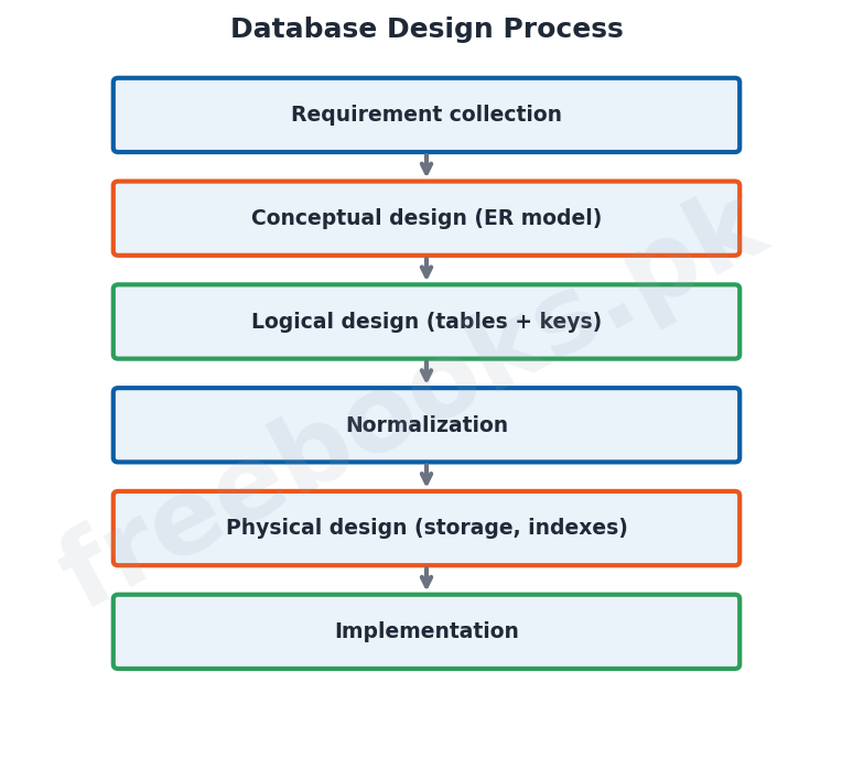
Database design is the process of planning the structure of a database before it is created, so that it stores all the required data without unnecessary duplication and can be used efficiently. A poorly designed database wastes space, allows errors and is hard to change, while a well-designed one is accurate, efficient and easy to maintain. Design is carried out in a series of steps, beginning with understanding the users’ requirements.
Data Modeling, Entities and Relationships
Data modeling means representing the data of the real world in a form that can be stored in a database. The main building blocks are entities and relationships. An entity is a real-world object about which data is kept, such as a student or a course, and it becomes a table. A relationship is an association between entities, such as a student ‘takes’ a course. Identifying the entities, their attributes and the relationships between them is the heart of database design.
Cardinality and Modality
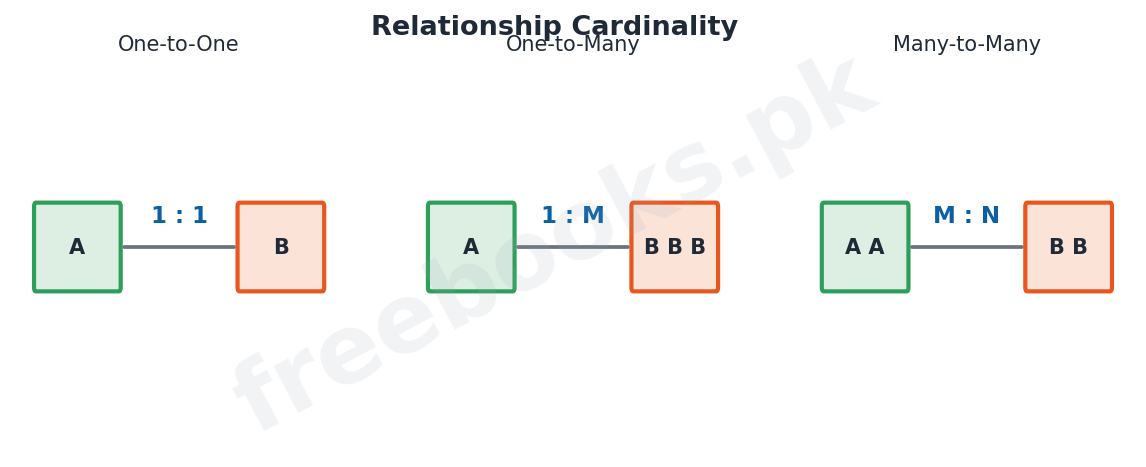
The relationships between entities are described by their cardinality and modality. Cardinality states how many instances of one entity may be related to instances of another; the three types are one-to-one (1:1), one-to-many (1:M) and many-to-many (M:N). For example, one class has many students, so the relationship between class and student is one-to-many. Modality states whether a relationship is optional or compulsory, that is, whether an instance must take part in the relationship or not.
The Entity-Relationship Diagram
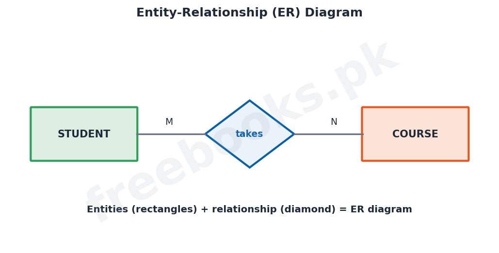
An entity-relationship diagram (ERD) is a picture that shows the design of a database. In an ERD, entities are drawn as rectangles, the attributes may be shown as ovals, and relationships are drawn as diamonds joining the entities, with the cardinality marked on the connecting lines. The ERD gives a clear, visual overview of the whole database and is used as the plan from which the actual tables are created.
From ER Model to Tables and Normalization
Once the ER model is complete, each entity is turned into a table with a primary key, and the relationships are represented by placing foreign keys or by creating extra tables. The tables are then improved by a process called normalization, which reorganises the data to remove redundancy (duplicated data) and to avoid errors when data is inserted, updated or deleted. Normalization splits large, badly organised tables into smaller, well-structured ones linked by keys.
Physical Database Design
After the logical design (the tables and keys) is fixed, the physical database design decides how the data will actually be stored on the computer for good performance. This involves estimating the volume of data and how it will be used, deciding how the data will be distributed and how the files will be organised, choosing which fields to index for fast searching, and defining integrity constraints, which are rules that keep the data correct (for example, that a mark must be between 0 and 100).
Implementation
Implementation is the final stage, in which the completed design is turned into a working database using a DBMS such as Microsoft Access. The tables are created with their fields, data types and keys; the relationships, indexes and integrity constraints are set up; and the database is then filled with data and tested. Once it works correctly the database is put into use, and later it is maintained and improved as needs change.
Important Definitions
Database design
Planning the structure of a database before creating it.
Data modeling
Representing real-world data in a form suitable for a database.
Entity
A real-world object about which data is stored (becomes a table).
Relationship
An association between entities.
Cardinality
How many instances of one entity relate to another (1:1, 1:M, M:N).
ER diagram
A diagram showing entities and their relationships.
Normalization
Reorganising tables to remove redundancy and avoid errors.
Integrity constraint
A rule that keeps the data in the database correct.
Key Facts & Rules
| Item | Detail |
|---|---|
| Entity | A thing -> a table |
| Relationship | Association between entities (a diamond in an ERD) |
| Cardinality types | 1:1, 1:M, M:N |
| ERD symbols | Rectangle = entity, oval = attribute, diamond = relationship |
| Normalization | Removes redundancy; splits into linked tables |
| Physical design | Storage, file organisation, indexes, integrity constraints |
Diagrams & Illustrations
Entity-relationship diagram: an ER diagram with two entities (STUDENT and COURSE) joined by a relationship (takes), with cardinality marked.
Database design process: the steps of database design from requirement collection through conceptual, logical, physical design and implementation.
Relationship cardinality: the three kinds of cardinality: one-to-one, one-to-many and many-to-many.
Solved Examples & Practice
Identify entities
In a school database, STUDENT, TEACHER and CLASS are entities; each becomes a table.
State the cardinality
One class contains many students, so the CLASS to STUDENT relationship is one-to-many (1:M).
Read an ERD
In an ERD, a rectangle stands for an entity and a diamond for a relationship between entities.
Why normalize
If a customer’s address is repeated in every order, normalization moves it to a separate CUSTOMER table to remove the duplication.
Short Questions & Answers
What is database design?
The process of planning the structure of a database before it is created, so it stores data correctly and efficiently.
What is an entity? Give an example.
A real-world object about which data is stored, such as a student; it becomes a table.
What is cardinality? Name its types.
How many instances of one entity relate to another; the types are one-to-one, one-to-many and many-to-many.
What is an ER diagram?
A diagram that shows the entities of a database and the relationships between them.
What is normalization?
The process of reorganising tables to remove redundancy and avoid errors during insert, update and delete.
What is an integrity constraint?
A rule that keeps the data correct, for example that a mark must be between 0 and 100.
Long Questions & Answers
Q1: Explain data modeling, entities, relationships and cardinality in database design.
Before a database is built it must be carefully designed, and the first and most important part of this design is data modeling, which means representing the data of the real world in a form that can be stored in a database. The two main building blocks of a data model are entities and relationships. An entity is a real-world object or thing about which the organisation needs to keep data, such as a student, a teacher, a course or a book; each entity usually becomes a table in the database, and the properties we store about it, such as a student’s roll number and name, are its attributes. A relationship is an association or connection between entities that reflects how they are related in the real world; for example, a student takes a course, or a teacher teaches a class, so ‘takes’ and ‘teaches’ are relationships. When two entities are related, we describe the relationship by its cardinality, which states how many instances of one entity can be linked to instances of the other. There are three kinds of cardinality. In a one-to-one (1:1) relationship, each instance of one entity is related to just one instance of the other. In a one-to-many (1:M) relationship, one instance of the first entity is related to many instances of the second, as when one class has many students. In a many-to-many (M:N) relationship, many instances of one entity are related to many of the other, as when many students take many courses. A related idea, modality, states whether taking part in a relationship is optional or compulsory. Correctly identifying the entities, their attributes and the cardinality of their relationships is the foundation of a good database design.
Q2: Describe the entity-relationship diagram and the process of turning a design into normalized tables.
Once the entities and relationships of a database have been worked out, they are drawn as an entity-relationship diagram, or ERD, which is a clear picture of the whole design. In an ERD, each entity is shown as a rectangle labelled with its name, the attributes may be drawn as ovals attached to the entity, and each relationship is shown as a diamond connecting the entities it joins; the cardinality of the relationship (such as 1, M or N) is written on the lines that link the diamond to the entities. Because it presents the entire structure visually, the ERD serves as the plan from which the actual database is built. The next step is to convert this ER model into tables: each entity becomes a table with a suitable primary key, and the relationships between entities are represented either by adding a foreign key to one of the tables or, for many-to-many relationships, by creating an additional linking table. These tables are then refined by a process called normalization, whose purpose is to organise the data so that each fact is stored in only one place. Normalization removes redundancy, that is, the unnecessary repetition of the same data, and in doing so it prevents the update, insertion and deletion problems that arise when duplicated data gets out of step. It works by splitting large, poorly organised tables into smaller, well-structured tables that are linked together by keys. The result is a set of clean, non-redundant tables that store the data efficiently and reliably.
Q3: Describe physical database design and the implementation of a database.
After the logical design of a database, that is, the set of normalized tables with their keys and relationships, has been decided, two further stages complete the process: physical design and implementation. Physical database design is concerned with how the data will actually be stored inside the computer so that the database performs well. In this stage the designer estimates the volume of data that the database will hold and studies how it will be used, that is, which data will be read and written most often; decides how the data should be distributed and how the files that hold it should be organised on the storage devices; chooses which fields should be indexed, since an index greatly speeds up searching on those fields; and defines the integrity constraints, which are rules built into the database to keep the data correct, such as insisting that a mark lies between 0 and 100 or that a roll number is never left blank. Good physical design makes the difference between a database that responds quickly and one that is slow. The final stage is implementation, in which the finished design is actually built using a database management system such as Microsoft Access. Here the tables are created with their fields, data types and primary keys; the relationships between tables, the indexes and the integrity constraints are set up; and the database is then loaded with data and thoroughly tested to make sure it works correctly. Once testing is successful, the database is put into everyday use, after which it is maintained and, from time to time, improved as the needs of its users change.
MCQs with Answers
Planning a database before building it is: (a) implementation (b) database design (c) normalization (d) indexing
Correct Answer: (b) database design.
A real-world object stored in a database is an: (a) attribute (b) entity (c) index (d) key
Correct Answer: (b) entity.
An association between entities is a: (a) relationship (b) tuple (c) field (d) view
Correct Answer: (a) relationship.
One class with many students is a ___ relationship: (a) one-to-one (b) one-to-many (c) many-to-many (d) none
Correct Answer: (b) one-to-many.
In an ERD an entity is drawn as a: (a) diamond (b) rectangle (c) oval (d) circle
Correct Answer: (b) rectangle.
In an ERD a relationship is drawn as a: (a) rectangle (b) diamond (c) oval (d) line
Correct Answer: (b) diamond.
Removing redundancy from tables is called: (a) indexing (b) normalization (c) modeling (d) backup
Correct Answer: (b) normalization.
A rule that keeps data correct is an: (a) index (b) integrity constraint (c) entity (d) attribute
Correct Answer: (b) integrity constraint.
Many students taking many courses is: (a) 1:1 (b) 1:M (c) M:N (d) none
Correct Answer: (c) M:N.
Turning the design into a working database is: (a) design (b) implementation (c) modeling (d) cardinality
Correct Answer: (b) implementation.
Quick Revision Summary
- Database design = planning the structure before building; done in steps.
- Data modeling: entities (things -> tables) + relationships (associations).
- Cardinality: 1:1, 1:M, M:N; modality = optional/compulsory.
- ERD: rectangle = entity, oval = attribute, diamond = relationship (with cardinality).
- Normalization removes redundancy; splits into linked tables.
- Physical design: storage, indexes, integrity constraints; then implementation in a DBMS. Notes by freebooks.pk.
Exam Tips
- Define entity and relationship with examples.
- Give the three cardinality types with examples.
- Know the ERD symbols (rectangle/oval/diamond).
- State the purpose of normalization (remove redundancy).
- Explain what physical design decides (indexes, constraints).
- Order the design steps ending in implementation.