
This chapter introduces digital systems and the branch of mathematics that underlies them: Boolean algebra. It begins by distinguishing analog signals (continuous, infinite values) from digital signals (discrete, only 0 or 1), and explains how Analog-to-Digital (ADC) and Digital-to-Analog (DAC) conversion allow real-world signals like sound to be processed by digital devices.
The chapter then covers the fundamental Boolean operations — AND, OR, and NOT — and the logic gates (AND, OR, NOT, NAND, XOR) that implement them in electronic circuits, along with truth tables that describe their behaviour. It introduces Boolean algebra's simplification laws and De Morgan's theorems, then applies these ideas to two important digital circuits, the half-adder and full-adder, and finally to Karnaugh maps (K-maps), a graphical technique for simplifying Boolean expressions.
Learning Objectives
- Differentiate between analog and digital signals, and explain ADC and DAC conversion
- Explain the fundamentals of digital logic and how binary values are represented as voltage levels
- Construct and evaluate Boolean functions and expressions using AND, OR, and NOT operations
- Build truth tables for logical expressions and Boolean functions
- Identify logic gates (AND, OR, NOT, NAND, XOR) and describe their functions
- Apply Boolean algebra laws and De Morgan's theorems to simplify Boolean expressions
- Describe the operation of half-adder and full-adder circuits using truth tables and Boolean expressions
- Use Karnaugh maps (K-maps) to minimize Boolean expressions
Key Concepts
3.1 Analog and Digital Signals
An analog signal changes smoothly and continuously over time and can take any value within a given range — examples include voice signals, body temperature, and radio waves. A digital signal, by contrast, has only two discrete values, represented as '0' and '1', and is used throughout digital electronics and computing systems.
Analog-to-Digital Conversion (ADC) converts continuous analog signals into discrete digital signals that can be processed by computers and smartphones; Digital-to-Analog Conversion (DAC) converts digital signals back into analog form so that humans can perceive the information, such as through speakers. For example, a microphone uses ADC to convert your voice into digital data for transmission, while a speaker at the receiving end uses DAC to convert that digital data back into sound waves.
3.2 Fundamentals of Digital Logic
Digital logic is the basis of digital systems, using binary values (0 and 1) to represent and manipulate information. In digital circuits, these two states are represented by different voltage levels — conventionally, a higher voltage (e.g., 5 volts) represents binary '1', while a low voltage (e.g., 0 volts) represents binary '0'. These voltage levels, called logic levels, allow digital circuits to switch devices on and off and to process information.
3.3 Boolean Functions: AND, OR and NOT Operations
Boolean algebra is a branch of mathematics dealing with logic and symbolic computation using two values, True and False. The AND operation requires two binary inputs and produces '1' only when both inputs are '1' (written A·B); otherwise the output is '0'. The OR operation produces '1' when at least one input is '1' (written A+B), and '0' only when both inputs are '0'. The NOT operation takes a single input and negates it (written Ā or ¬A): if the input is 1, the output is 0, and vice versa.
A Boolean function has one or more binary inputs and produces a single binary output, constructed by combining AND, OR, and NOT operations. For example, F(A,B,C) = A·B + Ā·C combines all three operations; its truth table is built by evaluating the function for every possible combination of A, B, and C. Boolean functions underpin the Arithmetic Logic Units (ALUs) of CPUs, data processing in memory and storage, and control logic throughout computers, phones, and calculators.
3.4 Logic Gates and their Functions
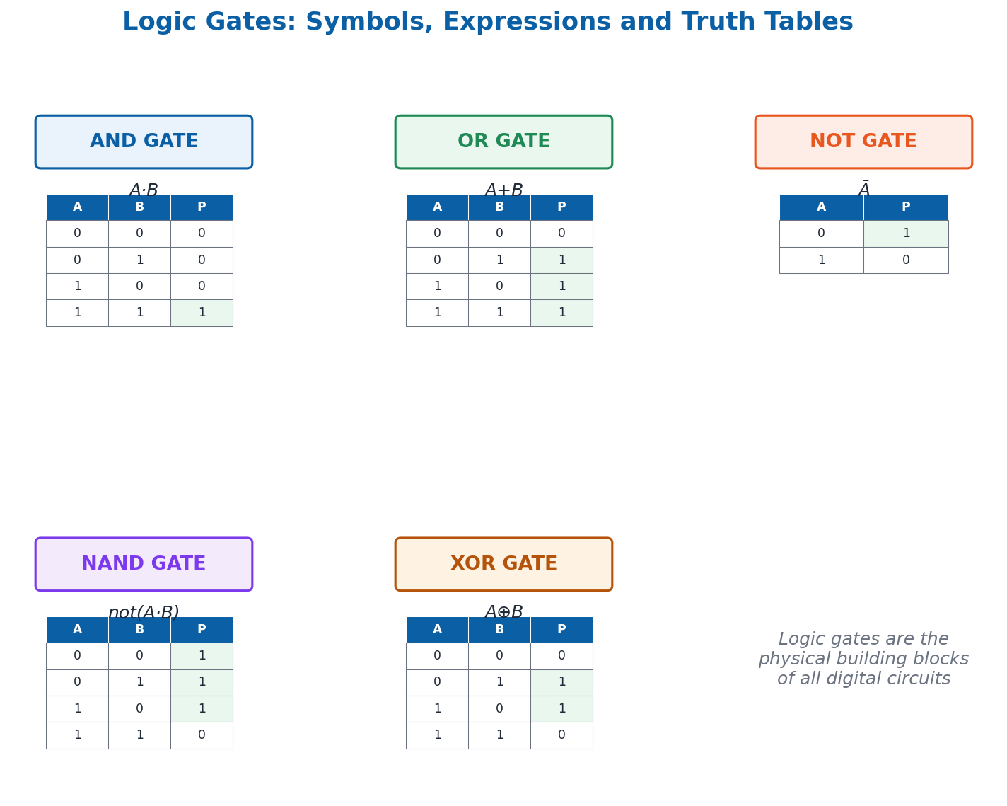
Logic gates are physical devices in electronic circuits that implement Boolean operations. The AND gate outputs true only when both inputs are true. The OR gate outputs true when at least one input is true. The NOT gate outputs the opposite of its single input. The NAND gate is an AND gate combined with a NOT gate — it is the inverse of AND, outputting true when at least one input is false.
The XOR (Exclusive OR) gate outputs true only when exactly one of its two inputs is true — unlike the OR gate, it outputs false when both inputs are true. For example, in a scenario where you can either play video games OR do homework but not both, XOR models this 'one or the other, not both' logic.
3.5 Boolean Algebra Laws and Simplification
Boolean expressions can be simplified using standard algebraic laws: Identity Laws (A+0=A, A·1=A), Null Laws (A+1=1, A·0=0), Idempotent Laws (A+A=A, A·A=A), Complement Laws (A+Ā=1, A·Ā=0), Commutative Laws (A+B=B+A, A·B=B·A), Associative Laws, Distributive Laws (A·(B+C)=A·B+A·C), and Absorption Laws (A+(A·B)=A).
De Morgan's Theorems state that the complement of a sum equals the product of the complements (Ā+B̄ = complement of A·B), and the complement of a product equals the sum of the complements (Ā·B̄ = complement of A+B). Simplifying Boolean expressions reduces the number of gates a circuit needs, making it faster, cheaper, and more energy-efficient.
3.6 Half-Adder and Full-Adder Circuits
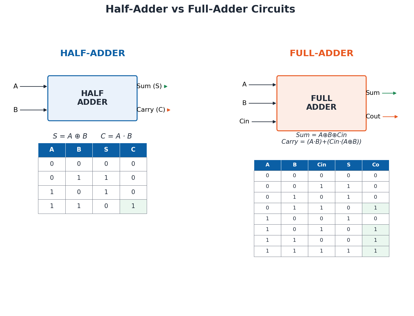
A half-adder is a basic circuit that adds two single-bit binary digits, with two inputs (A, B) and two outputs: Sum (S) and Carry (C). Its Boolean expressions are S = A⊕B (XOR) and C = A·B (AND) — the sum is high when only one input is high, while the carry is high only when both inputs are high.
A full-adder is a more complex circuit that adds three single-bit values: two data bits plus a carry-in bit (Cin) from a previous addition. It has three inputs (A, B, Cin) and two outputs: Sum and Carry-out (Cout). Its Boolean expressions are Sum = A⊕B⊕Cin and Carry = (A·B) + (Cin·(A⊕B)) — the sum is high when an odd number of inputs are high, while the carry is high when at least two inputs are high. Chaining full-adders together allows computers to add multi-bit binary numbers.
3.7 Karnaugh Maps (K-Maps)
A Karnaugh map (K-map) is a graphical method for simplifying Boolean expressions without lengthy algebraic manipulation, by plotting the truth values of a function in a grid so that patterns can be visually identified and combined. The size of the grid depends on the number of variables: a 2-variable K-map uses a 2×2 grid, a 3-variable K-map uses a 2×4 grid, and a 4-variable K-map uses a 4×4 grid.
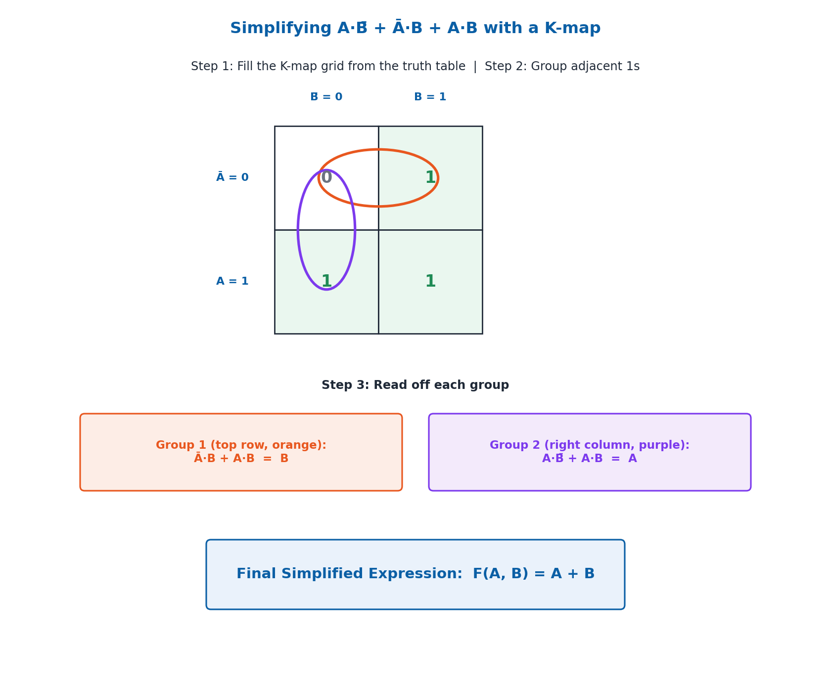
To build a K-map: create a grid sized for the number of variables, fill each cell with the output value (0 or 1) from the truth table, then group adjacent 1s into the largest possible groups (sized as a power of 2: 1, 2, 4, 8…). Each group of 1s corresponds to a simplified term. For example, simplifying A·B̄ + Ā·B + A·B with a 2-variable K-map identifies two groups that reduce to the much simpler final expression F(A,B) = A + B.
3.8 Minterms and Logic Diagrams
A minterm is a product term in which every variable of a Boolean function appears exactly once, in either its true or complemented form; each minterm corresponds to exactly one combination of variable values that makes the function equal to 1. For a 3-variable function A, B, C, the minterm where A=1, B=0, C=1 is written as A·B̄·C.
A logic diagram shows the physical arrangement of logic gates needed to implement a Boolean function, with each gate's inputs and outputs correctly connected. To build one: identify the gates needed for the function, arrange them according to the function's structure, then connect the inputs and outputs correctly — this is the final step that translates Boolean algebra into an actual, buildable digital circuit.
Important Definitions
What is a digital signal?
A signal that has only two discrete values, represented as '0' and '1', used throughout digital electronics and computing systems.
What is an analog signal?
A signal that changes smoothly and continuously over time and can take any value within a given range, such as sound waves or temperature.
What is Boolean algebra?
A branch of mathematics dealing with logic and symbolic computation, using two values (True/False or 1/0), forming the basis for digital circuit analysis and design.
What is a logic gate?
A physical device in an electronic circuit that implements a basic Boolean operation, such as AND, OR, NOT, NAND, or XOR.
What is a truth table?
A table that lists every possible combination of input values for a Boolean expression or logic gate, along with the corresponding output for each combination.
What is a half-adder?
A basic digital circuit that adds two single-bit binary digits, producing a Sum output (A⊕B) and a Carry output (A·B).
What is a full-adder?
A digital circuit that adds three single-bit values — two data bits and a carry-in bit — producing a Sum output and a Carry-out output, used to build multi-bit binary adders.
What is a Karnaugh map (K-map)?
A graphical grid-based method for simplifying Boolean expressions by plotting truth-table values and grouping adjacent 1s into the largest possible groups.
Key Facts and Relations
| Topic | Key Fact / Relation |
|---|---|
| AND operation | A · B → 1 only if both A=1 and B=1 |
| OR operation | A + B → 0 only if both A=0 and B=0 |
| NOT operation | Ā (or ¬A) → inverts the single input |
| XOR operation | A ⊕ B → 1 only if exactly one input is 1 |
| De Morgan's Theorems | Ā+B̄ = complement of (A·B); Ā·B̄ = complement of (A+B) |
| Half-adder | Sum (S) = A ⊕ B; Carry (C) = A · B |
| Full-adder | Sum = A ⊕ B ⊕ Cin; Carry = (A·B) + (Cin·(A⊕B)) |
| K-map grid size | 2 variables = 2×2; 3 variables = 2×4; 4 variables = 4×4 |
Diagrams
Logic Gates: Symbols and Truth Tables: A comparison of the AND, OR, NOT, NAND, and XOR logic gates, showing their standard symbols and truth tables side by side
Half-Adder and Full-Adder Circuits: Block diagrams of the half-adder (2 inputs, Sum/Carry outputs) and full-adder (3 inputs, Sum/Carry-out outputs) with their truth tables and Boolean expressions
Simplifying a Boolean Expression with a K-map: A worked 2-variable Karnaugh map example showing how A·B̄ + Ā·B + A·B is grouped and simplified to F(A,B) = A + B
Short Questions & Answers
Define a Boolean function and give an example.
A Boolean function is a function with one or more binary inputs that produces a single binary output, built using AND, OR, and NOT operations; for example, F(A,B) = A·B represents the AND operation between A and B.
What is the significance of the truth table in digital logic?
A truth table lists every possible combination of input values along with the corresponding output, making it possible to fully understand, verify, and communicate the behaviour of a Boolean expression or logic circuit.
Explain the difference between analog and digital signals.
An analog signal changes continuously and can take any value within a range (like sound waves), while a digital signal has only discrete values, 0 or 1, making it more resistant to noise and easier for computers to process.
Describe the function of a NOT gate with its truth table.
A NOT gate takes a single binary input and outputs its opposite: when the input is 0, the output is 1, and when the input is 1, the output is 0. Its truth table has two rows: A=0→P=1, A=1→P=0.
What is the purpose of a Karnaugh map in simplifying Boolean expressions?
A K-map provides a visual, grid-based way to identify and group adjacent 1s in a truth table, allowing a Boolean expression to be simplified into a shorter, equivalent form without lengthy algebraic manipulation.
What is the difference between a half-adder and a full-adder?
A half-adder adds only two single-bit inputs (A, B) and has no carry-in, while a full-adder adds three inputs (A, B, and a carry-in bit Cin), allowing full-adders to be chained together to add multi-bit binary numbers.
What is a minterm in Boolean algebra?
A minterm is a product term in which every variable of a Boolean function appears exactly once, in either its true or complemented form, corresponding to exactly one input combination that makes the function equal to 1.
Why are digital signals preferred over analog signals for data transmission and storage?
Digital signals are much less affected by noise and signal degradation than analog signals, making them better suited for reliably transmitting and storing information over long distances.
Long Questions & Answers
Explain the usage of Boolean functions in computers, with examples of where they are applied.
What are Boolean functions, and why are they fundamental to computers?
Boolean functions are mathematical expressions built from binary variables combined using the fundamental logical operations of AND, OR, and NOT. They form an essential foundation underlying the operation of virtually every modern computing device, from the simplest pocket calculator to the most powerful supercomputer, because every piece of information inside a digital computer is ultimately represented using nothing more than binary values of 0 and 1. Boolean functions provide the exact mathematical framework needed to meaningfully combine, manipulate, and process these binary values in order to produce useful results.
How are Boolean functions used in arithmetic operations?
One of the most widespread applications of Boolean functions is in arithmetic operations, where the Arithmetic Logic Unit (ALU) inside a computer's CPU relies on carefully designed Boolean functions, implemented as physical logic-gate circuits, to perform operations such as addition, subtraction, multiplication, and division on binary numbers. For instance, half-adder and full-adder circuits, built entirely from Boolean AND, OR, and XOR gates, form the core building blocks that allow a computer's ALU to add together binary numbers of any length.
How are Boolean functions used in data processing and control logic?
Boolean functions are essential for data processing, since binary data stored in a computer's memory and storage devices must constantly be manipulated, filtered, compared, and retrieved — Boolean logic provides the precise mechanism for making these binary decisions and comparisons at high speed. Boolean functions also play a crucial role in control logic, coordinating and controlling the various parts of a computer system so that different hardware and software components operate together in the correct, carefully synchronized sequence rather than working against one another.
How are Boolean functions used in everyday digital devices like phones and calculators?
Boolean functions are present in many everyday digital devices that people interact with constantly, such as cell phones and calculators. In a cell phone, every button press or touchscreen tap is ultimately evaluated internally by Boolean functions that determine whether specific conditions are true or false, and use this evaluation to generate the correct output or action. Similarly, when a person enters numbers and operations into a basic calculator, the device relies internally on Boolean logic circuits to correctly process this binary input and produce the correct final result.
Describe how to construct a truth table for a Boolean expression, using F(A, B, C) = A·B + Ā·C as a worked example.
What is the general process for constructing a truth table, and how many rows does it need?
Constructing a truth table for a Boolean expression is a systematic, mechanical process: work through every possible combination of the input variables, one at a time, and calculate the corresponding output for each, organizing all the results into a table. The first step is to identify how many distinct binary input variables the expression contains, since this number determines exactly how many rows the truth table needs. For any expression containing n distinct binary variables, the complete truth table always requires exactly 2n rows, since that is the total number of possible combinations when each variable can independently be 0 or 1.
How many rows does the truth table for F(A,B,C) = A.B + A'.C need, and how are the input combinations listed?
The function F(A, B, C) = A.B + A'.C contains exactly three distinct binary input variables — A, B, and C — so its complete truth table requires exactly 2 to the power 3 = 8 rows, one for every possible combination of these three variables. These eight combinations are listed in a clear, consistently ordered sequence, most commonly by counting upward in standard binary order from 000 through to 111: 000, 001, 010, 011, 100, 101, 110, and finally 111, ensuring every combination is accounted for and none are omitted or duplicated.
Why are intermediate helper columns useful when building a truth table?
For each of the eight input combinations of F(A, B, C) = A.B + A'.C, it is helpful to calculate and record relevant intermediate values as their own helper columns before calculating the final output. For this expression, it is useful to record the intermediate value of A.B in one column, the intermediate value of A' (the logical negation of A) in a second column, and the intermediate value of A'.C in a third column. Breaking the calculation down step-by-step like this substantially reduces the chance of making a careless error.
How is the final output column calculated for F(A,B,C) = A.B + A'.C?
Once every necessary intermediate helper value has been correctly calculated and recorded for a given row, the final overall output column, F(A, B, C), can be calculated for that row simply by taking the two previously calculated intermediate values from the A.B column and the A'.C column, and combining them using the final OR operation specified in the original expression. Repeating this process for every one of the eight rows produces a complete truth table describing the function's behaviour across all its possible input combinations.
Compare and contrast half-adders and full-adders, including their truth tables, Boolean expressions, and typical circuit diagrams.
What is a half-adder, and what is its truth table?
A half-adder is a digital circuit designed to add together exactly two single-bit binary digits at a time, commonly labelled A and B. It has two binary inputs (A and B) and produces two binary outputs: a Sum output (S) and a Carry output (C). Its truth table has four rows: when A=0, B=0, both Sum and Carry are 0; when A=0, B=1 or A=1, B=0, the Sum is 1 and Carry is 0; and when A=1, B=1, the Sum is 0 and Carry is 1, reflecting that 1+1 in binary equals 10.
What are the Boolean expressions for a half-adder's Sum and Carry outputs?
A half-adder's input-output relationships can be captured algebraically using two Boolean expressions. The Sum output is calculated as S = A XOR B, using the Exclusive OR operation. The Carry output is calculated as C = A.B, using the simple AND operation. In terms of circuitry, a half-adder can be built using just a single XOR gate to produce the Sum output, together with a single AND gate to produce the Carry output — making it the simplest possible binary adding circuit.
What is a full-adder, and how does it differ from a half-adder?
A full-adder is designed to add together three single-bit binary values simultaneously, rather than only two: it takes the two primary data bits, A and B, plus a third input bit, Cin (carry-in), representing any carry already generated by a preceding addition step elsewhere in a larger calculation. Because it has one additional input compared to a half-adder, its truth table requires eight rows rather than four. Its Sum output is Sum = A XOR B XOR Cin, and its Carry-out output is Carry = (A.B) + (Cin.(A XOR B)).
How is a full-adder built from half-adders, and why does this matter?
A full-adder's circuit is most commonly and efficiently built by combining two half-adder circuits with one additional OR gate, which combines the two carry outputs generated by the internal half-adders into the full-adder's single Carry-out output. It is precisely the extra carry-in input a full-adder has (which a half-adder lacks) that allows multiple full-adder circuits to be chained together, with the carry-out of one stage feeding the carry-in of the next — letting a computer add binary numbers of any length, well beyond a single-bit half-adder's limit.
Simplify the Boolean function F(A, B) = A·B + A·B̄ using Boolean algebra rules, showing each step and the law applied. Also simplify F(A,B,C) = Ā + B̄ + AC using De Morgan's laws.
How is F(A,B) = A.B + A.B' simplified using the Distributive Law?
Simplifying F(A, B) = A.B + A.B' starts by noticing that the variable A is a common factor in both terms being added together. Applying the Distributive Law (X.Y + X.Z = X.(Y+Z)) in reverse, 'factoring' direction pulls this common factor A outside a set of parentheses, transforming the original expression into the equivalent factored form A.(B + B'). This is the first step toward the fully simplified result, and it relies entirely on recognizing the shared factor between the two original terms.
How do the Complement Law and Identity Law finish simplifying F(A,B) to just A?
After factoring, the sub-expression inside the parentheses, B + B', exactly matches the Complement Law (X + X' = 1), so B + B' simplifies directly to the constant value 1. Substituting this back transforms A.(B + B') into A.1. Applying the Identity Law (X.1 = X) one final time simplifies this down to simply A. Therefore, the fully simplified form of the original function is F(A, B) = A.
How does De Morgan's Theorem simplify F(A,B,C) = A' + B' + AC, and why is this useful in circuit design?
Applying De Morgan's Theorem to the first two terms of F(A,B,C) = A' + B' + AC shows that A' + B' is equivalent to the complement of (A.B), so the expression becomes complement(A.B) + AC. This shows how a sum-of-complements can always be rewritten as the complement of a product using De Morgan's theorem — a standard technique for converting an expression into a form using only NAND-style logic. This matters because NAND gates are among the cheapest and most common gates to manufacture, so circuit designers frequently use De Morgan's laws to redesign circuits using only NAND gates, reducing the number of gate types a manufacturer needs to stock.
Multiple Choice Questions (MCQs)
Which of the following Boolean expressions represents the OR operation? (A) A · B (B) A + B (C) Ā (D) A ⊕ B
Correct answer: (B) A + B. The OR operation is represented using the '+' symbol: A + B, producing 1 when at least one input is 1.
What is the dual of the Boolean expression A · 0 = 0? (A) A + 1 = 1 (B) A + 0 = A (C) A · 1 = A (D) A · 0 = 0
Correct answer: (A) A + 1 = 1. The dual of an expression is found by swapping AND with OR and swapping 0 with 1; the dual of A · 0 = 0 is A + 1 = 1.
Which logic gate outputs true only if both inputs are true? (A) OR gate (B) AND gate (C) XOR gate (D) NOT gate
Correct answer: (B) AND gate. The AND gate outputs true (1) only when both of its inputs are true (1); otherwise it outputs false (0).
In a half-adder circuit, the carry output is generated by which operation? (A) XOR operation (B) AND operation (C) OR operation (D) NOT operation
Correct answer: (B) AND operation. In a half-adder, the Carry output is generated by the AND operation: C = A·B, which is 1 only when both A and B are 1.
What is the decimal equivalent of the binary number 1101? (A) 11 (B) 12 (C) 13 (D) 14
Correct answer: (C) 13. 1101₂ = 1×2³ + 1×2² + 0×2¹ + 1×2⁰ = 8+4+0+1 = 13.
Which gate is the inverse of the AND gate? (A) OR gate (B) NOR gate (C) NAND gate (D) XOR gate
Correct answer: (C) NAND gate. The NAND gate is an AND gate combined with a NOT gate, producing the exact inverse output of a plain AND gate.
What is the output of the XOR gate when both inputs are 1? (A) 0 (B) 1 (C) Undefined (D) Depends on the circuit
Correct answer: (A) 0. The XOR gate outputs true only when exactly one input is true; when both inputs are 1, XOR outputs 0.
A K-map for a Boolean function with 3 variables uses which grid size? (A) 2×2 (B) 2×4 (C) 4×4 (D) 4×8
Correct answer: (B) 2×4. A 3-variable Karnaugh map uses a 2×4 grid, covering all 2³ = 8 possible input combinations.
Which of the following is an example of Analog-to-Digital Conversion (ADC)? (A) A speaker converting digital audio to sound (B) A microphone converting voice into digital data (C) A printer printing a document (D) A monitor displaying an image
Correct answer: (B) A microphone converting voice into digital data. ADC converts a continuous analog signal (like voice captured by a microphone) into discrete digital data; this is the opposite of DAC.
In a full-adder circuit, how many binary inputs are there in total? (A) 1 (B) 2 (C) 3 (D) 4
Correct answer: (C) 3. A full-adder has three binary inputs: A, B, and a carry-in bit (Cin) from a previous addition stage.
Quick Revision Summary
- Analog = continuous, infinite values; Digital = discrete, only 0 or 1; ADC converts analog→digital, DAC converts digital→analog
- AND (A·B) = 1 only if both are 1; OR (A+B) = 0 only if both are 0; NOT (Ā) = inverts the input; XOR (A⊕B) = 1 only if exactly one is 1
- NAND = inverse of AND; logic gates are physical implementations of Boolean operations
- Key Boolean laws: Identity, Null, Idempotent, Complement, Commutative, Associative, Distributive, Absorption, De Morgan's
- De Morgan's: complement of (A+B) = Ā·B̄; complement of (A·B) = Ā+B̄
- Half-adder: S=A⊕B, C=A·B (2 inputs, no carry-in); Full-adder: Sum=A⊕B⊕Cin, Carry=(A·B)+(Cin·(A⊕B)) (3 inputs, has carry-in)
- K-map grid size: 2 variables=2×2, 3 variables=2×4, 4 variables=4×4; group adjacent 1s in powers of 2 (1,2,4,8…) to simplify
- A minterm includes every variable of a function, in true or complemented form, corresponding to exactly one row where the function = 1
Exam Tips
- Memorize the four basic truth tables (AND, OR, NOT, XOR) — they are the foundation for every other question in this chapter
- For duality questions: swap every AND↔OR and every 0↔1 in the original expression
- Half-adder has NO carry-in; Full-adder HAS a carry-in (Cin) — this is the single most tested distinction in this chapter
- When simplifying Boolean expressions, always name the law used at each step (Distributive, Complement, Identity, etc.) — this is usually required for full marks
- For K-map questions, remember: group size must always be a power of 2 (1, 2, 4, 8…), and groups must be adjacent (including wrap-around edges)
- Practice building truth tables methodically: for n variables, there are always exactly 2ⁿ rows, listed in binary counting order